Engine Freshen, 4 Speed Conversion

Rzeppa

Rising Sun Member
Joined
Aug 24, 2005
Messages
8,828
Location
Kittredge CO, USA
wesintl said:
Yeah.. my xfer fell right off too. Are you going to be around sat morning? I have some errands to run all over town and I'd like to get it mostly back together this weekend.:cheers:
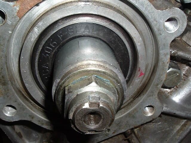
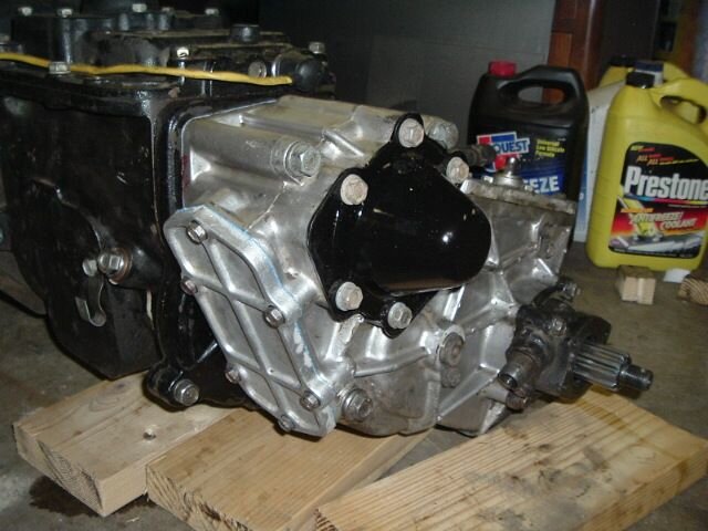
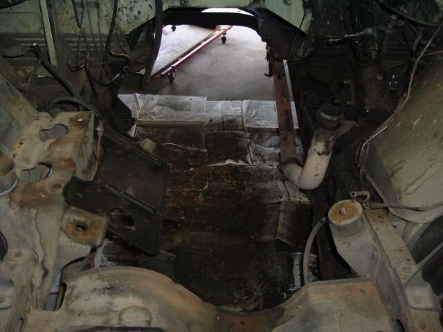
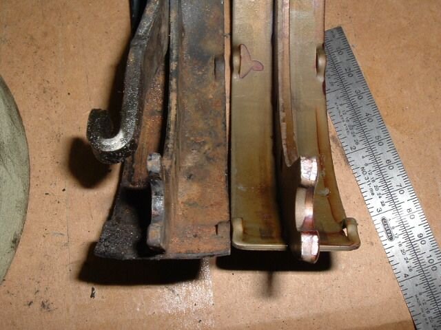
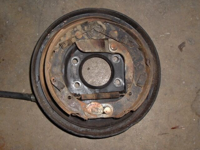
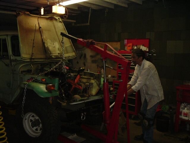
Yes, I plan to be. I just got the spacer cut for the t-case to replace the PTO gear, now I need to clean up the cuts and get the length to the same 1.918" that the PTO gear was. Then get the t-case back on today and install tomorrow. I was just looking in the engine compartment and realized I still have a few more tasks in there before I hoist the whole mess in there. Oh yeah, just remembered...gotta put new shoes in the parking brake. Unless I cut my crossmember off I won't be going in there any time soon ;-)

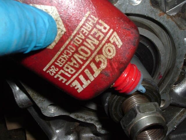
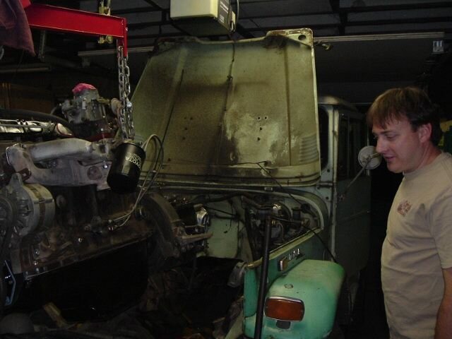
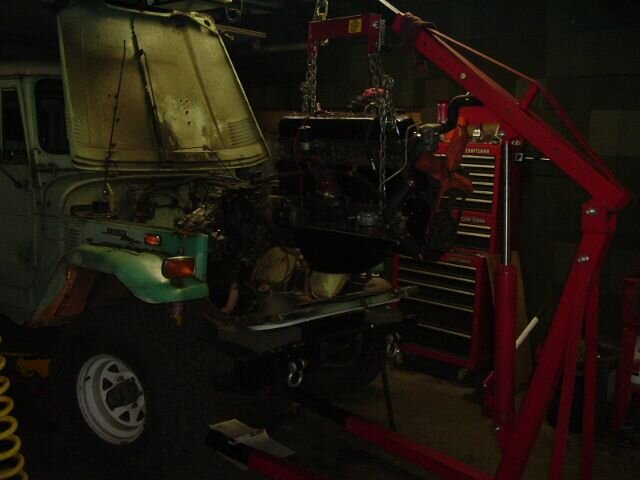
But yeah, the plan is to start positioning the engine into the rig Saturday morning, so I'll be around. Bonus for you! SOR sent me a 3 speed front tranny seal instead of the 4 speed seal I ordered, so it's all yours...
 

Rzeppa

Rising Sun Member
Joined
Aug 24, 2005
Messages
8,828
Location
Kittredge CO, USA
This morning I got the distributor positioned properly, after a few tries. Note how the rotor is positioned, pointing right at the middle bolt of the side cover, per the FSM. After that, the FSM has you rotate the body of the dist until the points are just starting to open, as shown in the photo. This will give plenty of rotation for static advance if needed, before the vacuum diaphragm hits the dipstick tube.

The bottom photo is with the cap, plugs, plug wires, and the rest of the ignition wiring in place.
 

Attachments

  • 2006_0714Image0068.JPG
    2006_0714Image0068.JPG
    41.4 KB · Views: 550
  • 2006_0714Image0069.JPG
    2006_0714Image0069.JPG
    52.1 KB · Views: 489

Rzeppa

Rising Sun Member
Joined
Aug 24, 2005
Messages
8,828
Location
Kittredge CO, USA
When I took the motor out, I noticed that the (usual) driver's side motor mount had broken. I swapped the good passenger side over to the driver's side, and JB Welded the other one, which will be installed on the passenger side where it won't see any tension, only compression.
 

Attachments

  • 2006_0714Image0070.JPG
    2006_0714Image0070.JPG
    44.3 KB · Views: 477
Last edited:

Rzeppa

Rising Sun Member
Joined
Aug 24, 2005
Messages
8,828
Location
Kittredge CO, USA
This is the spacer I made from 1.25 sch40 pipe, shown next to the PTO gear it will replace. The PTO gear was 1.918, the spacer is 1.924, I don't think the .006" difference will cause a problem. The way the helical cut gears of the input geat and the idler work, is the torque of the engine forces the input gear rearward into the spacer and then into the inner race of the input shaft bearing. There is another spacer which goes behind the bearing which is secured with a large flat washer and a stake nut to the end of the input shaft. This is where everything gets pushed. As long as there is some play in the assembly (I measured .050" when I took it out), all's well.

I took quite a bit of time making sure the ends were square and even. In the photo you can see a little divot from where the bench grinder caught it, but on the end it's pretty flat. I measured about .002" out of flat, and figured that's about the best I can do without a lathe.
 

Attachments

  • 2006_0714Image0071.JPG
    2006_0714Image0071.JPG
    54.7 KB · Views: 433
Last edited:

Rzeppa

Rising Sun Member
Joined
Aug 24, 2005
Messages
8,828
Location
Kittredge CO, USA
Here's a photo of the Datsun B210 bearing. I measured it carefully inside and out before driving it in. It turns out that the coarse 10 spline output shaft of the 3 speed tranny is just a little bigger than the fine, 16 spline 4 speed input shaft, hence the need for the special bearing.

In the bottom photo, the tranny-to-transfer case seal is installed. There has been some debate about which way the lip is supposed to face, toward the tranny or toward the t-case. The factory one I took out had the seal facing the tranny (outward from the t-case housing), so that's how I put the new one in. I didn't drive it in, I took the old one out with my fingers and put the new one in with my fingers; I didn't want to mess up the lip.
 

Attachments

  • 2006_0714Image0073.JPG
    2006_0714Image0073.JPG
    58.5 KB · Views: 444
  • 2006_0714Image0074.JPG
    2006_0714Image0074.JPG
    50.8 KB · Views: 435

Rzeppa

Rising Sun Member
Joined
Aug 24, 2005
Messages
8,828
Location
Kittredge CO, USA
I got the t-case, gear, spacer and bearing all slid onto the tranny output shaft. I peeked inside to see how the spacer looked. All was well, but I couldn't get the bolts threaded in. The only one I could get started was the lower one on the inside. I took the whole mess back out to make sure the bolts had the proper threads. They did and I tried again, still to no avail.
 

Attachments

  • 2006_0714Image0076.JPG
    2006_0714Image0076.JPG
    38.8 KB · Views: 428
  • 2006_0714Image0075.JPG
    2006_0714Image0075.JPG
    53.9 KB · Views: 453

Rzeppa

Rising Sun Member
Joined
Aug 24, 2005
Messages
8,828
Location
Kittredge CO, USA
On a hunch, I took a bolt out of the t-case of my 76 resto and compared it to the one from my 71. Sure enough, it was longer! It turns out that the threads in the 3 speed tranny start right at the tranny housing, but on the 4 speed H42 they start a ways inside. A call to Stevinson and I have the longer bolts on order, and will steal the ones off my 76 just for this project, so I can get it done this weekend.

Very important tip! If you are doing a 4 speed swap from a 3 speed rig, you need to obtain the bolts from a 4 speed rig to fasten the t-case to the tranny! The only one which you will be able to re-use is the lower inside bolt. The three long top ones and the upper inside one need to be for a 4 speed application!
 

Attachments

  • 2006_0714Image0077.JPG
    2006_0714Image0077.JPG
    49.9 KB · Views: 446

Rzeppa

Rising Sun Member
Joined
Aug 24, 2005
Messages
8,828
Location
Kittredge CO, USA
Well, I hit another roadblock yesterday. I went to install the spacer, washer and nut onto the back of the tranny output shaft, and they didn't fit! The top photo shows them being held next to the 3-speed tranny output shaft. Note how the shaft has a smaller diameter splined section in the rear. The spacer has a step inside too. The spacer is very thick walled, the locking washer has a tab to go into the keyway in the shaft, and the only provision to lock the nut is with the locking washer.

In the bottom photo, I am holding the same spacer next to the 4-speed output shaft. The ID of the spacer is too small, there is no keyway in the shaft to use the locking washer, and the nut has coarser threads than the shaft's threads.
 

Attachments

  • 2006071501.jpg
    2006071501.jpg
    47.6 KB · Views: 422
  • 2006071502.jpg
    2006071502.jpg
    60.9 KB · Views: 418

Rzeppa

Rising Sun Member
Joined
Aug 24, 2005
Messages
8,828
Location
Kittredge CO, USA
Well, I figured since the bolts from my 76 resto saved me on this before, I'd just steal the spacer, washer and nut off of it. I took them out of the 76 and put them onto the 71. The ID fit, and the nut fit (it's the exact same stake nuts that are used on pinions), but the spacer was too long! At this point I had one spacer that was too small ID, another one that was too long, and still had some of that sch40 1.25 pipe leftover from making the spacer for the inside. As to why the 4 speed spacer was too long, the only things I could think of was that the Datsun bearing must be thicker than the stock bearing, or that the inside of the 3 speed case was shallower than a 4-speed case? I didn't measure the thickness before I put it in, and I didn't feel like pulling the whole mess out to find out. But the important thing is that on the inside, the input gear is perfectly lined up with the idler gear when everything is forced onto the race of the bearing, so I figured the bearing must be in the right position.

The photo below shows the 4-speed spacer, and how if I had used it, there wouldn't be enough threads engaged on the stake nut to allow it to be staked to the groove on the end of the tranny output shaft:
 

Attachments

  • 2006071503.jpg
    2006071503.jpg
    51.2 KB · Views: 1,294

Rzeppa

Rising Sun Member
Joined
Aug 24, 2005
Messages
8,828
Location
Kittredge CO, USA
One option would have been to take everything apart and shorten the inside spacer, the one I made to take the place of the PTO gear. That would move everything forward and allow the use of the 4 speed rear spacer, by moving the bearing forward in the case. The option I chose however, was to make yet another custom spacer from my pipe.

The length of spacer to get the nut in the right spot on the output shaft to get a good stake and yet hold it snug against the bearing race was 1.330". I took a "belts and suspenders" approach and used some lock tight on the threads before I snugged the nut down. The bottom photo is the whole thing installed with the nut staked.

Shortly after I cut the spacer, Wes showed up and we ended up chatting for a good long time. By the time I got around to installing it, it was getting late and I gave up for the evening.
 

Attachments

  • 2006071505.jpg
    2006071505.jpg
    63.7 KB · Views: 407
  • 2006071504.jpg
    2006071504.jpg
    47.5 KB · Views: 433

Rzeppa

Rising Sun Member
Joined
Aug 24, 2005
Messages
8,828
Location
Kittredge CO, USA
I went ahead and cleaned up and painted the rear t-case cover, then installed it and the inspection cover.
 

Attachments

  • 2006_0717Image0022.JPG
    2006_0717Image0022.JPG
    53.5 KB · Views: 406

Rzeppa

Rising Sun Member
Joined
Aug 24, 2005
Messages
8,828
Location
Kittredge CO, USA
While I still had everything out and the tranny hump off, I scraped and cleaned up a bunch of stuff on the floorboards, framerails and everywhere else I could reach easily.
 

Attachments

  • 2006_0717Image0023.JPG
    2006_0717Image0023.JPG
    48.9 KB · Views: 402

Rzeppa

Rising Sun Member
Joined
Aug 24, 2005
Messages
8,828
Location
Kittredge CO, USA
I took a photo of the e-brake before I took it apart to install the new OEM shoes, so I could remember how all the parts go together. It turned out that the new shoes had thicker frames than the ones that were in there, which explained why I couldn't get the c-clips into the grooves on the pins. After WAY too much time trying to get them in, I finally compared the frame thicknesses (second photo), and found out the problem.

So I resigned myself to having to reuse the old shoes. What I did was resurface the old shoe surfaces with a medium 3M abrasive wheel, the lower two photos are before (massively glazed) and after (like new) shoe surfaces.
 

Attachments

  • 2006_0717Image0030.JPG
    2006_0717Image0030.JPG
    46.3 KB · Views: 381
  • 2006_0717Image0029.JPG
    2006_0717Image0029.JPG
    39.3 KB · Views: 399
  • 2006_0717Image0028.JPG
    2006_0717Image0028.JPG
    56.8 KB · Views: 407
  • 2006_0717Image0024.JPG
    2006_0717Image0024.JPG
    52.8 KB · Views: 391
Last edited:

Rzeppa

Rising Sun Member
Joined
Aug 24, 2005
Messages
8,828
Location
Kittredge CO, USA
Scott Yoder (Jaderunner on this forum) came over this evening to help me put the engine in. With the bellhousing, clutch, tranny and t-case hanging off the back it was an unwieldy thousand pounds of metal. The load leveler was helpful to a point, but the rear chains proved to be a problem: we couldn't get it far enough back before the rear chain would hit against the firewall.
 

Attachments

  • 2006_0717Image0031.JPG
    2006_0717Image0031.JPG
    44.5 KB · Views: 400
  • 2006_0717Image0032.JPG
    2006_0717Image0032.JPG
    36.3 KB · Views: 388

Rzeppa

Rising Sun Member
Joined
Aug 24, 2005
Messages
8,828
Location
Kittredge CO, USA
We got the front passenger side mount bolted up, then worked on getting the other three lined up. Using a five foot pipe as a lever, we almost got them lined up before my JB Welded motor mount broke again.
 

Attachments

  • 2006_0717Image0033.JPG
    2006_0717Image0033.JPG
    50.6 KB · Views: 389

Rzeppa

Rising Sun Member
Joined
Aug 24, 2005
Messages
8,828
Location
Kittredge CO, USA
Using one floor jack under the t-case and another one under the tranny, I took the load leveler off and substituted a single chain on the front engine hook. With this approach, we were able to get the other three motor mounts fastened. Then we hoisted a Molsen and called it a good night.
 

Attachments

  • 2006_0717Image0034.JPG
    2006_0717Image0034.JPG
    34.3 KB · Views: 382
  • 2006_0717Image0035.JPG
    2006_0717Image0035.JPG
    38.3 KB · Views: 390

Shark Bait

Rising Sun Member
Joined
Aug 23, 2005
Messages
5,029
Location
Parker, CO
Jeff,

Are you sure about your clutch slave bracket pic/caption? The next picture looks like the one to me.

I have several newer style motor mounts if you need some. And I've got a ton of extra motor mount brackets, too.
 

JadeRunner

Rising Sun Member
Joined
Aug 23, 2005
Messages
1,837
Location
Lakewood, CO
Sorry I broke the motor mount. I wasn't using enough finesse with the big pry bar I guess.

Let us know that the engine fired up this morning.
 
Back
Top