Engine Freshen, 4 Speed Conversion

Rzeppa

Rising Sun Member
Joined
Aug 24, 2005
Messages
8,881
Location
Kittredge CO, USA
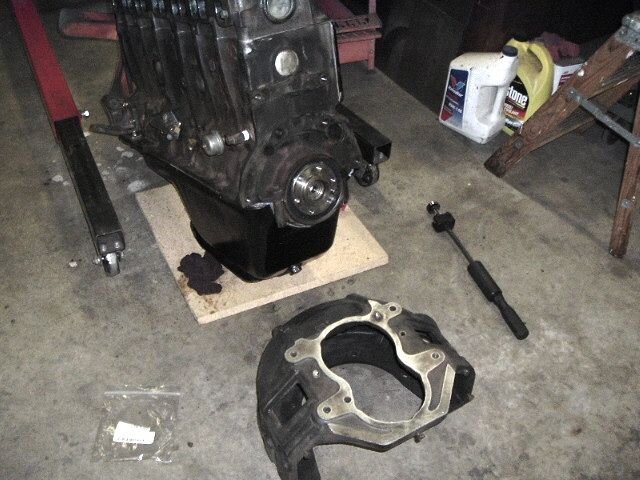
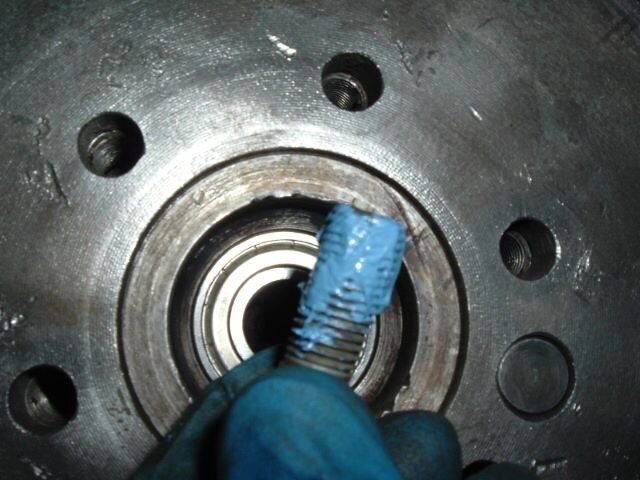
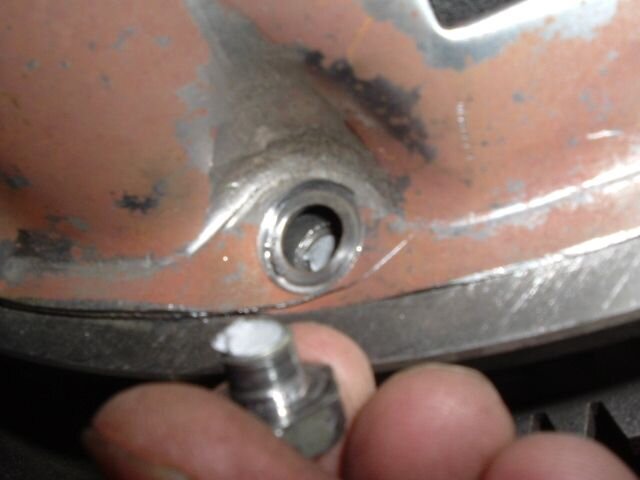
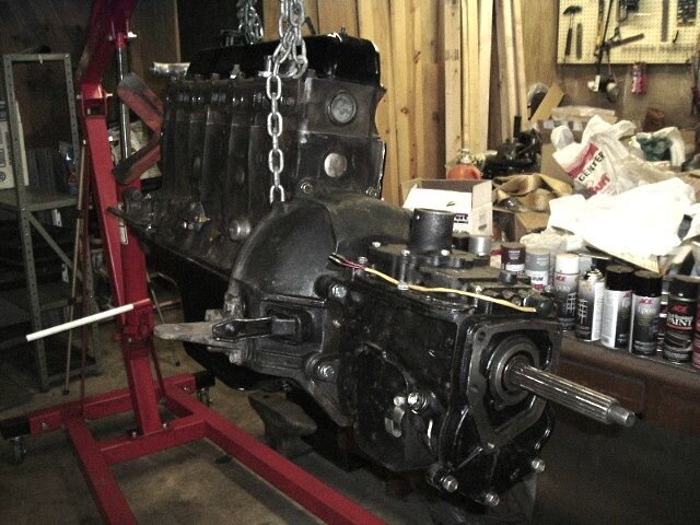
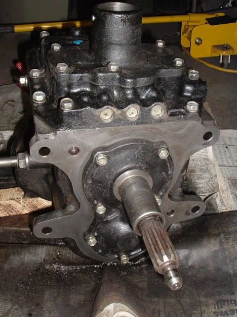
After cleaning. I had ordered in a new input shaft seal, so I took the front bearing retainer off, only to discover that the seal didn't match. A little investigation revealed that I had ordered the right one, but they sent one for a 3-speed instead. Since it had never leaked from there before, I decided to just button it up and move on. I had to use the reverse light switch out of the 76, another part I'll need to get another one of for the 76.
 

Attachments

  • 2006_0703Image0157.JPG
    2006_0703Image0157.JPG
    68.6 KB · Views: 452

Rzeppa

Rising Sun Member
Joined
Aug 24, 2005
Messages
8,881
Location
Kittredge CO, USA
I went to move the clutch fork pivot from the passenger side of the bellhousing to the driver's side to match my 3-speed clutch parts. On a lark I went to check and make sure it was the same for a 3-speed and a 4-speed, and it wasn't! The short one on the left is a 4-speed pivot, and the longer one on the right is a 3-speed clutch fork pivot. Which one to use? It'll probably be obvious once the flywheel and clutch are installed, but I'd prefer to put this in before I install the bellhousing. Anybody know?
 

Attachments

  • 2006_0703Image0158.JPG
    2006_0703Image0158.JPG
    95.5 KB · Views: 442

subzali

Hard Core 4+
Joined
Aug 22, 2005
Messages
10,762
Location
Denver CO
It's actually a 13/16, and you're right the belt slips. Now why in the world did I learn to do that in the first place then? :confused: I know I've had to do it and there was a reason for it...:confused: oh well looks good Jeff, someday I'll have all the little projects mostly done and maybe be brave enough to dig into something like this engine freshen project...:thumb:

Rzeppa said:
With proper (read=not overtight) tension on a belt, it will slip before you can turn the engine with just the belt. If a belt is so tight that it won't slip to turn the engine, the bearings of whatever it's connected to (water pump, alternator, smog pump, etc.) will wear out prematurely. This is something I've learned over the years through painful experience :-(

One last comment on turning an engine by hand: Taking out the spark plugs always makes it MUCH easier unless your compression is so low you have bigger problems than valve adjustment ;-)
 

Rzeppa

Rising Sun Member
Joined
Aug 24, 2005
Messages
8,881
Location
Kittredge CO, USA
Last night, I gave up when I couldn't get the pilot bearing out with my slide hammer style pilot bearing puller. I went to heat it with my MAPP gas torch, ran out of gas about 10 seconds after I fired it up, so I decided that was a message to quit for the night. This morning, I got out the O-A rig, heated it up a little, and it popped right out!
 

Attachments

  • 2006_0704Image0159.JPG
    2006_0704Image0159.JPG
    52.6 KB · Views: 425

Rzeppa

Rising Sun Member
Joined
Aug 24, 2005
Messages
8,881
Location
Kittredge CO, USA
The flywheel bolts have to have sealant applied to their threads prior to installing them. The holes in the back of the crank go all the way through, and this would be a leak point without the sealant. Torque spec is 47 foot pounds. After torqueing them down, the tabs on the locking plates are bent onto a bolt head flat.
 

Attachments

  • 2006_0704Image0161.JPG
    2006_0704Image0161.JPG
    53.1 KB · Views: 418

Rzeppa

Rising Sun Member
Joined
Aug 24, 2005
Messages
8,881
Location
Kittredge CO, USA
Flywheel installed, friction plate lined up with alignment tool, the pressure plate is ready for install.
 

Attachments

  • 2006_0704Image0162.JPG
    2006_0704Image0162.JPG
    68.4 KB · Views: 434

Rzeppa

Rising Sun Member
Joined
Aug 24, 2005
Messages
8,881
Location
Kittredge CO, USA
Mama told me there'd be days like this. D'oh!!! I was tightening the pressure plate mounting bolts and this one snapped off. Knowing that I will now have to remove the pressure plate and friction plate, drill it out, retap and reinstall everything, I decided to take a break and upload the photos for now. At this point, I'm not sure if I'll have enough time to do all that and then install the fork and then stab the tranny before I have to get cleaned up for the evening's festivities. It will kind of depend on how long it will take to get the broken bolt out. After I drill a pilot hole, I'll try my left handed drill bits and cross my fingers that it will unthread itself instead of the hard way.
 

Attachments

  • 2006_0704Image0163.JPG
    2006_0704Image0163.JPG
    29 KB · Views: 437

Rzeppa

Rising Sun Member
Joined
Aug 24, 2005
Messages
8,881
Location
Kittredge CO, USA
Thank goodness for left handed drill bits. After I got the flywheel out onto the floor, getting the stub of the broken bolt took all of 30 seconds! 'Course it took an hour to take everything apart and put it all back together! I used all brand new M8x1.25x20 bolts and new lock washers. Didn't want to take a chance with old fasteners this time. BTW, this is the last clutch kit I'll buy from Carolina Clutch. The reman pressure plate wasn't flat and round at the edges, which is what caused this issue in the first place. The bolts were being used to make the edges conform to the shape/dimensions of the step where it sets in the flywheel.

But, all's well that ends well. I think I have just enough time to get the fork installed and stab the tranny before I have to get cleaned up and call it a day. Yee hah!
 

Rzeppa

Rising Sun Member
Joined
Aug 24, 2005
Messages
8,881
Location
Kittredge CO, USA
Yesterday, I got this bright idea to get one of those "load leveler" dohickies for the end of my cherry picker so I could point the assembled engine/bellhousing/tranny/t-case forward or backward, up or down. After I brought it home, I went about installing it on the end of my cherry picker. It came with two wimpy chains, so I decided to use my more robust chains, but they were too long. I cut one in half and used the two ends on the new toy. Then I put the tranny on my creeper and edged it up to the engine, with the engine suspended at the same height as the tranny input shaft. I used some scrap 2x6 pieces of lumber to keep the tranny level.
 

Attachments

  • 2006_0705Image0074.JPG
    2006_0705Image0074.JPG
    71.6 KB · Views: 403

Rzeppa

Rising Sun Member
Joined
Aug 24, 2005
Messages
8,881
Location
Kittredge CO, USA
It took a lot of wrangling as I sat astride of the tranny to get the input shaft started into the splines of the friction plate. As the splines finally engaged, I heard a scraping noise but didn't think about it, I was sweaty and tired. I knew that I had the friction plate aligned with the pilot bearing with the alignment tool prior to starting the procedure, and it *should* just be a matter of tightening things down, pressing the end of the tranny input shaft into the center race of the pilot bearing. I had gotten a set of four 12mm x 1.25mm x 40 mm bolts at the hardware store in the morning, since I couldn't find any spare sets in my parts stashes. They didn't reach yet to get the threads started, so I continued to manhandle the tranny into the clutch.

Using c-clamps on the lower ears, I was able to get the tranny input shaft farther into the friction plate, and got the bolts started. I used the bolts to pull the tranny into the clutch. After a certain point, the tranny was about 1/4" from the bellhousing and tightening the bolts was getting harder and harder. They required way more torque than I knew was necessary; something was wrong. I took a break and stared at the whole thing for a while, trying to think of what might be wrong. After a bit of thought, I realized that the scraping noise I heard may have been the friction plate slipping out of center, and that the nose of the tranny input shaft was now trying to press into the side of the pilot bearing.

I looked at my watch and realized I had a meeting to get ready for, so I loosened the bolts and called it a night. The photo below is as far as I got.
 

Attachments

  • 2006_0705Image0075.JPG
    2006_0705Image0075.JPG
    77.8 KB · Views: 421
Last edited:

Rzeppa

Rising Sun Member
Joined
Aug 24, 2005
Messages
8,881
Location
Kittredge CO, USA
Patience, Grasshopper

This morning, I took the tranny back off and peered into the clutch with a drop light, and sure enough, the friction plate had shifted when I engaged the splines. After carefully checking that the pilot bearing wasn't damaged and still spun smoothly, I loosened the clutch and recentered the friction plate with an alignment tool.

Then, I used utmost patience before using brute force to stab the tranny. I got out a bullet level, and carefully tweaked both the height and the angle of the engine to precisely match the tranny input shaft and SHAZZAM! Click, it went right in like a two dollar...well you know what I mean ;-)

Before I took this photo, I had snugged up the tranny bolts and added a new rubber boot to the clutch fork. The boot didn't want to slip on until I remembered the window gasket trick of using window cleaner on the edges. In the lower photo, the boot for the unused passenger side is installed. You can see the clutch slave mounting bosses in the bellhousing engine mount ear, so I am guessing these are 4 speed mounting ears. The driver's side one, where I will have to mount my 3-speed slave may not be right, so if necessary I'll swap it out when I pull the one out of the rig.
 

Attachments

  • 2006_0706Image0076.JPG
    2006_0706Image0076.JPG
    59.6 KB · Views: 413
  • 2006_0706Image0077.JPG
    2006_0706Image0077.JPG
    77.4 KB · Views: 408

Rzeppa

Rising Sun Member
Joined
Aug 24, 2005
Messages
8,881
Location
Kittredge CO, USA
Yee hah! Engine, clutch and tranny are finally one! I jacked the whole thing up to test out the new load leveler, it worked great so far. We'll see how it behaves with a t-case on the back of the tranny! Notice in the lower photo how the load leveler is adjusted so that even with the tranny in the rear, the whole assembly is level.
 

Attachments

  • 2006_0706Image0078.JPG
    2006_0706Image0078.JPG
    70.9 KB · Views: 412
  • 2006_0706Image0079.JPG
    2006_0706Image0079.JPG
    74.5 KB · Views: 402
Last edited:

Rzeppa

Rising Sun Member
Joined
Aug 24, 2005
Messages
8,881
Location
Kittredge CO, USA
Stupid hardware store bolts are DIN/ISO, which means that m12 threads have 19mm heads instead of the proper 17mm heads, This creates clearance problems in a lot of places. When I pull the 3-speed, I'll swap these out, but they hold down the fort for now.
 

Attachments

  • 2006_0706Image0080.JPG
    2006_0706Image0080.JPG
    95.1 KB · Views: 416

Rzeppa

Rising Sun Member
Joined
Aug 24, 2005
Messages
8,881
Location
Kittredge CO, USA
Before I pulled the old engine, I peeked inside my t-case to see if I had a PTO gear. Sure enough, there it is. I checked into getting a spacer, but John at Coyote Cruisers and Jeremiah Proffitt both said to just make one from some tubing or pipe, so I picked up some 1.25" sch40 at Home Depot.
 

Attachments

  • 2006_0710Image0081.JPG
    2006_0710Image0081.JPG
    64.6 KB · Views: 397
Last edited:

Rzeppa

Rising Sun Member
Joined
Aug 24, 2005
Messages
8,881
Location
Kittredge CO, USA
I had to take the tranny hump out to get to the linkages to unhook them. Of course that means taking the seats out and lifting the fuel tank. Notice the double nuts on the linkage on the right. That's because one day the nut fell off, leaving me with only 2nd and 3rd gear, no first or reverse. That was fun getting home that day.
 

Attachments

  • 2006_0710Image0082.JPG
    2006_0710Image0082.JPG
    74.1 KB · Views: 400
  • 2006_0710Image0083.JPG
    2006_0710Image0083.JPG
    89.5 KB · Views: 396

Rzeppa

Rising Sun Member
Joined
Aug 24, 2005
Messages
8,881
Location
Kittredge CO, USA
I took a couple shots of the clutch slave so I could remember how it's supposed to mount. It'll be a little different when I put it back because of getting rid of the tranny linkages.
 

Attachments

  • 2006_0710Image0086.JPG
    2006_0710Image0086.JPG
    68.4 KB · Views: 412
  • 2006_0710Image0084.JPG
    2006_0710Image0084.JPG
    87.1 KB · Views: 414

Rzeppa

Rising Sun Member
Joined
Aug 24, 2005
Messages
8,881
Location
Kittredge CO, USA
I also photographed the t-case range linkage, again to see what it's supposed to look like when I put everything back together. The photo at the bottom is the rod that I will have to cut and lengthen to accomodate the longer 4 speed tranny.
 

Attachments

  • 2006_0710Image0087.JPG
    2006_0710Image0087.JPG
    54.8 KB · Views: 402
  • 2006_0710Image0088.JPG
    2006_0710Image0088.JPG
    46 KB · Views: 400

Rzeppa

Rising Sun Member
Joined
Aug 24, 2005
Messages
8,881
Location
Kittredge CO, USA
Every time I turned around, there was still something else that needed to be disconnected or somehow removed. It took longer than I expected, but then that's always how these things go.
 

Attachments

  • 2006_0710Image0089.JPG
    2006_0710Image0089.JPG
    66.9 KB · Views: 389
Back
Top