Rzeppa
Rising Sun Member
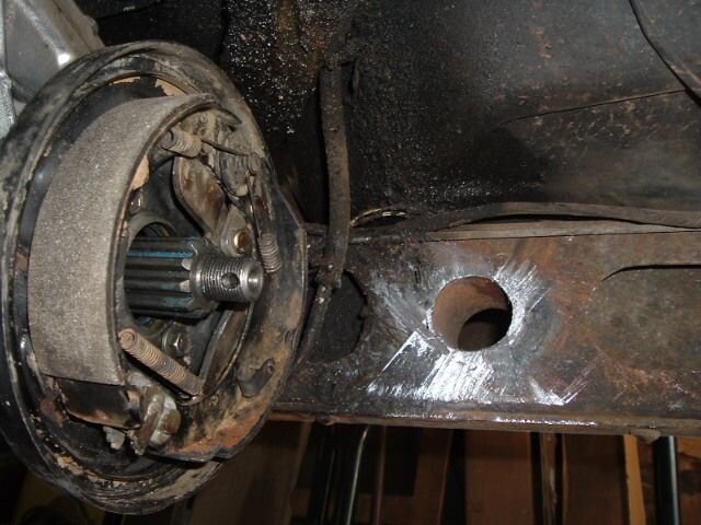
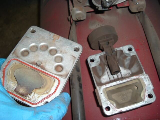
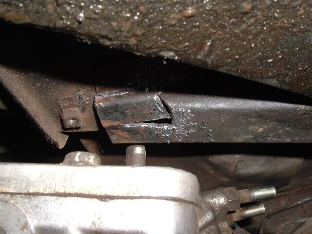
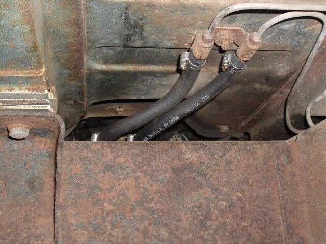
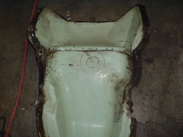
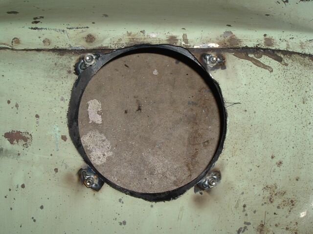
#93 is the driver's side, where the 3 speed slave will go. #94 is the passenger side, where a 4 speed slave would go. I went back and looked at my earlier pix of the still-mounted slave, and I'm just not sure, but fortunately I have all the bits that came off of it. There was a bunch of column shift linkage stuff on the slave mount area, not sure what gets re-used and what doesn't.Shark Bait said:Jeff,
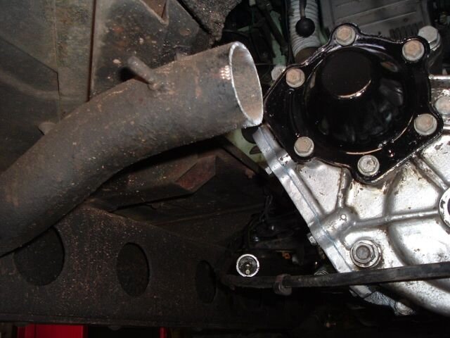
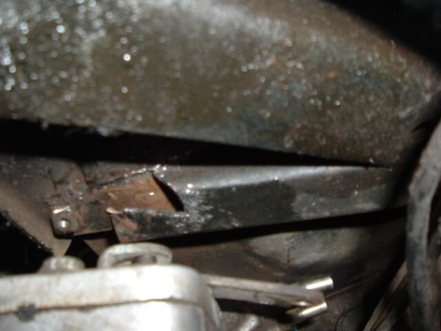
Are you sure about your clutch slave bracket pic/caption? The next picture looks like the one to me.
I may have to take you up on that. Right now I have 3 options (make that 4 with your offer, thanks Chris!). (1) leave it as-is for now. It's the compression (passenger) side and probably won't make much difference, I can replace it some other time, (2) steal one off my 76 and order in another one to replace it (3) order in a new one and wait however long for it to come in (next Monday most likely), or see about coming down to your place and bumming one off you.Shark Bait said:I have several newer style motor mounts if you need some. And I've got a ton of extra motor mount brackets, too.
At this point I haven't decided yet. Scott and I worked pretty late last night and I'm a little burned out on wrenching, I'll see about getting back after it later this afternoon. At a minimum I want to see if the engine will fire up and run on all 6 cylinders before I start bolting everything back up.
 So, it's not all your fault.
")