Engine Freshen, 4 Speed Conversion

Rzeppa

Rising Sun Member
Joined
Aug 24, 2005
Messages
8,828
Location
Kittredge CO, USA
Hulk said:
So you're going to floor shift for the tranny, but maintaining the vacuum shift for the transfer case? Why not make both floor shift?
(1) It would be even more work, (2) More parts to procure, (3) I like the existing arrangement.
Hulk said:
Great write up!
Thanks! I wish there had been something this detailed available before I started. Little things like the t-case bolts and the rear t-case spacer wouldn't have been such surprises. In any case, after I finish I'll move the whole article over to my own web space...after seeing how many views this thing has gotten I can only imagine how much B/W this is costing us ;-)
 

Rzeppa

Rising Sun Member
Joined
Aug 24, 2005
Messages
8,828
Location
Kittredge CO, USA
After I drilled pilot holes into the stack of 4 plates, I picked one and clamped it to where I will weld it to the inside frame rail. I used the existing pilot holes as markers to drill pilot holes through the frame rail, so they line up precisely. These plates are also marked so I know the exact orientation.

There are always a lot of stupid little times sinks in any project like this. For example, when I was drilling the pilot holes in the frame rail, it was taking forever. I finally took a break, got out my drill doctor and sharpened the bit. It ultimately took less time to get out the drill doctor, sharpen the bit and put the drill doctor away, than it would have taken if I just kept struggling with a dull bit.
 

Attachments

  • 2006_0725Image0053.JPG
    2006_0725Image0053.JPG
    68.3 KB · Views: 426
Last edited:

Rzeppa

Rising Sun Member
Joined
Aug 24, 2005
Messages
8,828
Location
Kittredge CO, USA
Next, I drilled two plates at 17/64 to tap for M8x1.25 threads, and two plates with 3/8 through holes. I also drilled the inside of the frame rail at 17/64 for the M8 tap. Then I tapped the two plates, and then clamped one to the inside frame rail and tapped all the way through the frame. There wasn't enough clearance for the t-handle so I had to use an open end wrench to turn the tap.
 

Attachments

  • 2006_0725Image0056.JPG
    2006_0725Image0056.JPG
    51 KB · Views: 422
Last edited:

Rzeppa

Rising Sun Member
Joined
Aug 24, 2005
Messages
8,828
Location
Kittredge CO, USA
Here's the plate welded to the frame. I couldn't get a solid bead because I didn't want too much heat going on here. To the left is the fuel line, where you can see a makeshift heat shield I made out scrap sheet metal. Along the top is a brake line and a section of wiring harness, which I didn't want to overheat. So basically I used the same techniques I use when welding sheet metal and don't want to get it so hot that it warps the metal. Another thing I did is after every few weld spots, I blasted it with compressed air to cool it down. Combined with the threads through the frame rail itself, I'm pretty sure it will hold up.
 

Attachments

  • 2006_0725Image0057.JPG
    2006_0725Image0057.JPG
    85 KB · Views: 435

Rzeppa

Rising Sun Member
Joined
Aug 24, 2005
Messages
8,828
Location
Kittredge CO, USA
I welded nuts to the back side of the other threaded plate, then I used magnets to position it for welding. You can see how I marked the plates for orientation: when they were clamped together in a stack, I ground a groove along one set of edges, seen at the bottom of the photo, then I made a small mark with a sharpie pen on the "top" of each of the plates. This assures that all four holes will line up, since I don't have CNC equipment to do precision machining.
 

Attachments

  • 2006_0725Image0058.JPG
    2006_0725Image0058.JPG
    50.2 KB · Views: 445
Last edited:

Rzeppa

Rising Sun Member
Joined
Aug 24, 2005
Messages
8,828
Location
Kittredge CO, USA
I bolted the free plates to the welded plates to figure out how much to trim the crossmember. Not shown, is how much time it took to get the ends of the crossmember perfectly lined up and exactly the right length. I guessed that it should have taken about 15 minutes to a half hour, but it actually took more like 2 hours. After I cut the ends rough with the chop saw, I kept grinding, test fitting and grinding some more until it was just right. Then I tacked it, took it out and welded up some good beads.

It is a LOT easier to weld downward than upward! When you are welding on the underside of something, the molten puddle keeps wanting to drip down. These beads aren't a work of art like Ian's, but they'll do.
 

Attachments

  • 2006_0725Image0059.JPG
    2006_0725Image0059.JPG
    42.1 KB · Views: 425
  • 2006_0725Image0060.JPG
    2006_0725Image0060.JPG
    50.1 KB · Views: 433

Rzeppa

Rising Sun Member
Joined
Aug 24, 2005
Messages
8,828
Location
Kittredge CO, USA
After the welding, I painted the crossmember and welded plates with some zero rust and set it aside to dry while I busied myself with other tasks. I connected the speedometer cable to the t-case (it reaches!) and connected the e-brake cable to the lever under the dash. The latter was a total PITA, trying to get the eye end of the cable in exactly the right location to slide the pin through. Anyone who's worked under a dash will tell you what fun it is...not! The little blue objects at the lower left are where I tore pieces off my gloves.

I spent quite a bit of time adjusting the clutch slave rod. It needed to be lengthened as far as it would go, and it's just close quarters in there. It's located right above the driver's side engine mount ear and it's hard to get vice grips positioned to grab onto the shaft to hold it while you turn the adjusting endcap.

I connected the 4 speed reverse light switch to the existing wiring near where the 3 speed linkage used to be near the steering box. The old switch never worked unless you held the shift lever a certain way, so it will be cool having backup lights again!

After the wiring, I went to put the tranny hump in. Even with the hole cut for the shift tower and the fuel tank held up out of the way, it was still a struggle to get it in there up under the back of the heater. The 4 speed tranny sits taller than the old 3 speed did.
 

Attachments

  • 2006_0725Image0061.JPG
    2006_0725Image0061.JPG
    77.7 KB · Views: 423

Rzeppa

Rising Sun Member
Joined
Aug 24, 2005
Messages
8,828
Location
Kittredge CO, USA
It took a while to get the tranny hump bolted in. I ended up having to clearance the hump hole by making small cut-outs with a dremel for a couple of the tranny top plate bolts. Next I put the shifter in. The top photo shows the order they go in, and shows why you need to rotate clockwise for removal and counterclockwise for install. It's tough to put in or take out without the SST, as that little spring takes a good bit of downward force to compress enough to get the slots lined up with the pins inside the shift tower. I made a makeshift SST with a short section of 1.5" pipe with teeth cut into the end to get some bite on the dome.

After that, I installed the boot. At the bottom edge you can see a little section where I had to cut a little out to clear a tranny top plate bolt.
 

Attachments

  • 2006_0726Image0063.JPG
    2006_0726Image0063.JPG
    45.1 KB · Views: 457
  • 2006_0726Image0062.JPG
    2006_0726Image0062.JPG
    49.2 KB · Views: 599

Rzeppa

Rising Sun Member
Joined
Aug 24, 2005
Messages
8,828
Location
Kittredge CO, USA
Next I installed the crossmember. It's in exactly the factory location, and there is about a half inch of clearance between the rear of the e-brake drum and the bottom of the crossmember. If I need to service the e-brake, now I just have to unbolt that section of crossmember.
 

Attachments

  • 2006_0726Image0064.JPG
    2006_0726Image0064.JPG
    44.7 KB · Views: 497

Rzeppa

Rising Sun Member
Joined
Aug 24, 2005
Messages
8,828
Location
Kittredge CO, USA
After I installed the exhaust, I spent some time rerouting the speedo cable, e-brake cable and reverse switch wiring. Previously, they had been too close to the exhaust and part of the e-brake cable jacket had melted. Also, they were laying across the clutch fork, and I didn't want them rubbing.
 

Attachments

  • 2006_0726Image0065.JPG
    2006_0726Image0065.JPG
    52 KB · Views: 422

Rzeppa

Rising Sun Member
Joined
Aug 24, 2005
Messages
8,828
Location
Kittredge CO, USA
I went to install the driveshafts, and noticed that the stupid driveshaft shop had installed the new u-joint I gave them 180° wrong. It's tough to see in the photo, but the zerk on the righthand u-joint is oriented downward and should be upward, opposite the one on the left. I started to R&R it, but then decided to just put it in for now. I'll take it back out later and make them put the u-joint in right.
 

Attachments

  • 2006_0726Image0066.JPG
    2006_0726Image0066.JPG
    44 KB · Views: 414

Rzeppa

Rising Sun Member
Joined
Aug 24, 2005
Messages
8,828
Location
Kittredge CO, USA
After the driveshafts, I filled the tranny and t-case with 90wt and went back to the engine compartment. The rest went pretty fast: battery, radiator, fill coolant, front bib, puke tank, air cleaner and PCV breather. I put the driver's seat in, but was anxious to take her for a test drive so I didn't bother with the passenger seat.

I drove her around the block and immediately noticed not much power, an exhaust leak and that the clutch disengages right at the floor. After a good warm-up, I pulled back in and tightened up the downpipe flange and manifold, set the timing (14° is where I ended up) and lengthened the clutch pedal rod as far as it would go. After it had cooled down a bit I topped off the coolant now that the t-stat had a chance to open.

Then I drove down to the gas station and filled up (almost $48! Yikes!), and drove around some more. The clutch doesn't feel right, but it does work. I'll never buy another clutch from Carolina Clutch - the reman pressure plate didn't fit right to begin with, and I am guessing that they didn't adjust the height of the fingers properly. There's some gear noise from the timing gears - couple of chipped teeth and mismatch, they'll wear in after a few thou miles. The lifters are a little noisy, hopefully they'll wear in too. With the timing advanced more the pep and power is good. Oil pressure is good, temperature is good, no spewing leaks. I'll drive her some more today and go back in to do a hot adjustment on the valves, and inspect for good oil to the rockers.

Anyway, she's back to driving under her own power. 4WD works, hi/lo range works, no major issues. Besides adjusting the valves, I still need to put the passenger seat and front floor mats in, figure out what to do about skid plates (3-speed vs modified 4-speed plate) and put the spare back on.

Once I get this article onto my own web space, I'll edit my first post with a link to it. Happy cruisin'!
 

Attachments

  • 2006_0726Image0067.JPG
    2006_0726Image0067.JPG
    53.8 KB · Views: 414
  • 2006_0726Image0068.JPG
    2006_0726Image0068.JPG
    53.6 KB · Views: 416
Last edited:

Rzeppa

Rising Sun Member
Joined
Aug 24, 2005
Messages
8,828
Location
Kittredge CO, USA
Hulk said:
Congrats, Jeff! Your write up was great, and I'm sure that you're glad to be 99.9% finished with the job. How do you like the floor shift?
Thanks Matt. Yes, I am VERY glad for this project to be done. I don't like some of the sounds I hear when I drive her, but I know some of them will go away: the new transition in the t-case mated with the old idler make a heck of a whine. Same with the mismatched new cam and old crank timing gears, plus there's tooth or two chipped on the crank timing gear from a long time ago which is audible. The lifters are noisy, hopefully that will settle down as they wear in to their new home. There's still a small exhaust leak, I am going to try using two donuts instead of just one on the down pipe. I hate the clutch, but it works. I should have reused the old pressure plate, but how can you know? I have both the slave rod and the pedal rod adjusted as far as they will go, but the disengagement point is still right near the floor. I may see if I can readjust the pressure plate fingers from underneath with the dust cover off. The floor shift is same-same as my 76 and 78, in fact the tranny came out of the 76, so nothing new there. I miss the three on the tree, leaving the hump uncluttered for the knees of a middle passenger in the front bench seat, but AFAIK they don't make a four on the tree ;-)

I drove her to the store and back today, total of 30 miles on the clock since the rebuild, so far so good. It's nice having enough compression that I can take my foot off the pedal when going downhill and she slows down. She's got good power and doesn't vibrate, despite the untoward noises. The power will likely improve as the rings seat in with the honed cylinder walls; at that point I will probably have to back off on the timing advance as the compression increases.
 

IanB

0
Joined
Aug 23, 2005
Messages
811
Location
Just this side of reality.
Interesting crossmember design, I like the bolt on idea. I have to build one myself, do you see the load on the factory coss member as being tension, compression, shear or twist?
 

Rzeppa

Rising Sun Member
Joined
Aug 24, 2005
Messages
8,828
Location
Kittredge CO, USA
IanB said:
Interesting crossmember design, I like the bolt on idea. I have to build one myself, do you see the load on the factory coss member as being tension, compression, shear or twist?
My educated guess is that it's mostly twist, as in up and down rather than on-axis of the crossmember itself. Consider when the rear axle is articulating, one side wants to go up while the other wants to go down. I guess you might consider that a form of shear, but not in the classic sense.
 

Rzeppa

Rising Sun Member
Joined
Aug 24, 2005
Messages
8,828
Location
Kittredge CO, USA
Epilog:

With over 10,000 miles on the whole setup, she runs smooth and strong, starts right up in subzero weather, the engine and gear noise is much quieter and all is well. Compression is 120-125 across the board (about the best you can get at 7000 feet elevation), no leaks to the concrete and I'm a happy camper. Total engine refresh cost was about $150 in rings and bearings; I already had a gasket and seal kit lying around.

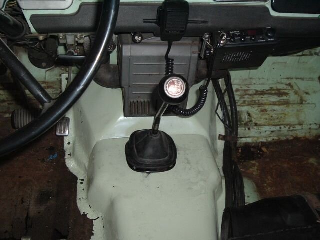
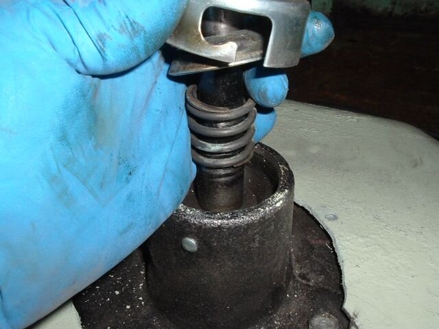
Since the last installment, I did inspect the fingers of the pressure plate from underneath and discovered that one of them was adjusted so bad it wasn't even touching the T-O bearing. I couldn't loosen the lock nut on the finger to re-adjust the finger, so I fabricated a cup shaped spacer out of a nut and bolt and slipped it in over the bolt end of the finger, it makes the fingers pretty close to even. I also lengthened the slave rod a bit more, and the clutch works much better and shifting is smoother. I should have kitted the tranny while it was on the floor, 2nd gear synchro is pretty shot, but still serviceable. The tranny had 272k miles on it when I put it in, now has 282k, not too bad :-)

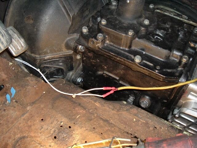
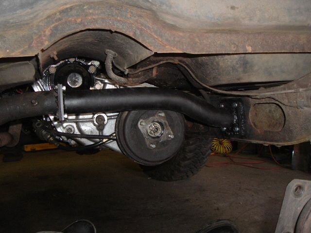
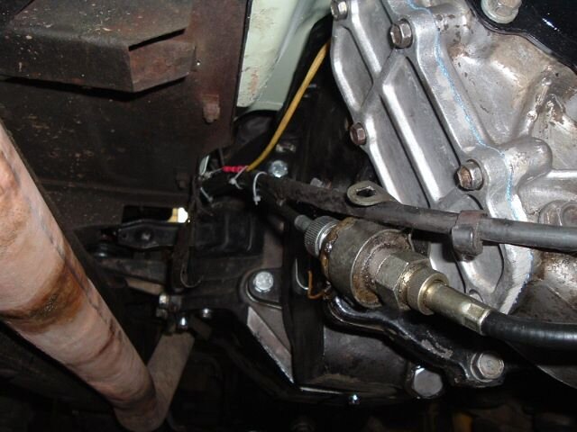
I really like the 4 speed tranny/3-speed t-case combo, and have wheeled it hard. My internal t-case spacers and so forth seem to be holding up fine. I did do an oops when I mated the t-case to the tranny: even though I used a new seal, I did not use RTV on the output shaft splines and I got the classic t-case to tranny pumping. So I did the time-honored fix and drilled and tapped the fill holes, threaded in barb fittings and connected them with some 1/8 ID tubing. Seems to work fine.

I ended up using my 3-speed skid plate, I drilled 1" holes for the newly positioned 3.5" rearward drain plugs for the t-case and tranny, it has worked fine.

A lot of work, but not too much money, and I learned a lot along the way. Hopefully this write-up will help others too.

I haven't put this on my own web space yet, I am in the midst of completely redoing my personal web site. Prototype pages are here.

Happy Cruisin'!
 

Convert

Hard Core 4+
Joined
Aug 25, 2005
Messages
1,412
Thanks for the great write up Jeff this will definitely help when I start my 40 project
 
Back
Top