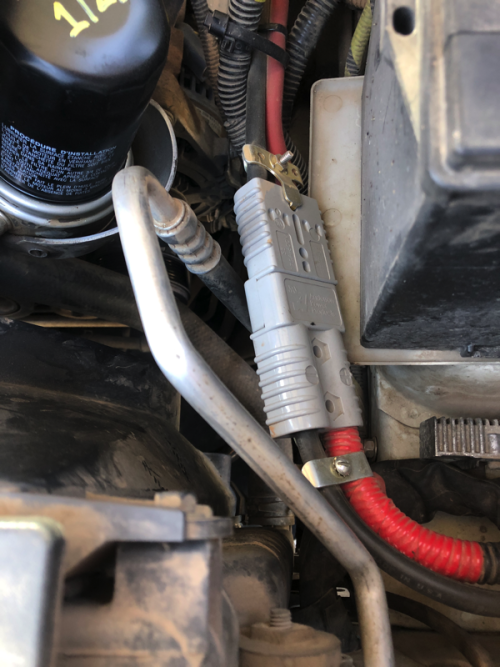
How would you size the connector?
Size them the same as you would cables or fuses, by looking at the current charts for time or temperature.
The two sizes you're probably considering are SB175 and SB350. We'll start with the SB350.
Anderson rates these at 500A for UL and 325A for CSA. To achieve this requires 350 MCM cable with 105°C insulation. Wire size 350 MCM is two steps larger than 4/0 (212 MCM), MCM meaning kcmil or thousands of circular mil cross sectional area.
IOW 1000 circular mil is 1 kcmil or 1 MCM, so these work with very large cables. The smallest wire Anderson makes a terminal for in SB350 is 1/0 AWG and I'm not sure there's any reducing bushing that will let you go smaller than this.
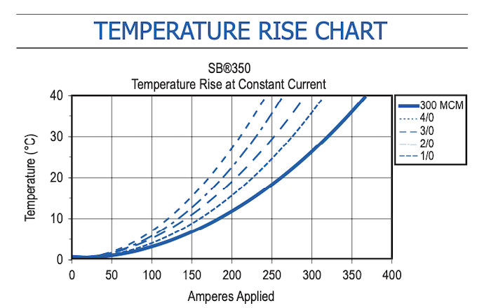
Then look at the temperature rise charts to get an idea. Here again we have to make a decision on absolute maximum in theory vs practical averages and real world. If you want the no question then you have to assume 478 amps and thus 350 MCM with an SB350. But that's not possible nor does anyone actually do that, right?
So assume you want to use a SB350 still but with a more realistic 1/0 size cable and ~280 amps sustained. The chart would suggest this isn't possible but you can extrapolate and guesstimate. I'd think we're talking perhaps 50°C rise, so maybe 90°C if ambient is 40°C. That still less than 105°C of the insulation so the circuit as a whole is solid, no worries really under any conditions or load.
So then the next question is what about 2 AWG or something like that? Warn supplies this size, maybe 1 AWG, I don't remember.
In any case now we have a problem in specifications. SB175 is too small on paper for this but the SB350 can't use 2 AWG without using a reducing bushing not specified by Anderson. So the tons of margin the SB350 gives isn't helpful since it's not possible to use practically.
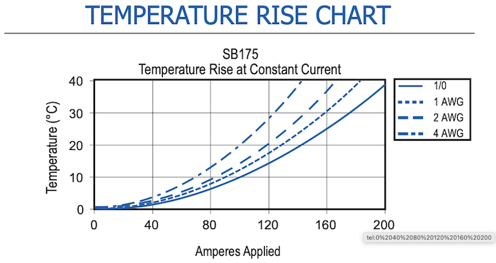
But Anderson only rates the SB175 for 340 amps and that's with 2/0 AWG (a lot smaller than the 478A theoretical) and if we go smaller the chart starts to look worrisome. We might be out of luck.
Even using our 1/0 AWG with ~280A we're far off the chart to the point that trying to best guess will be a huge guess. If I was trying I'd think 280 amps would suggest +55°C to +60°C rise. And this with 1/0 AWG, smaller stuff would be way up there.
So now we're probably beyond sharpening the pencil on an analysis to close this loop easily. Now we have to just make some assumptions and WAGs. First is to understand that the numbers given are steady state continuous current with no time limit.
So then one you can look at is the contact resistance. Anderson says with 6" of 1/0 AWG the mated contact resistance is 0.1 mΩ for the SB175 terminals.
Power is current squared times resistance. So 280^2 x (0.0001) = 7.84W. It would seem they are being very conservative in their ratings. That's fairly reasonable power to dissipate.
How does it compare to cables? 1/0 AWG pure copper is 0.000101277 Ω/foot, e.g. 0.11 mΩ/ft or 0.055 mΩ of that stated contact resistance, thus implying the contacts themselves are ~0.045mΩ. Now measuring contact resistance isn't an exact art. There's area of the mating surfaces, the force of the spring, how well the two surfaces mate (e.g. roughness, oxidation, etc.) and the shape and final cross section of the crimped area.
An aside, is why I constantly harp on
good crimpers, if you over crimp, meaning squish the shape too much or in a non-uniform shape (e.g. like a center lump and two "wings") or you slice strands off you may not end up with specified contact resistance. The same thing can happen with the ring lugs on the ends, you can create a section of higher resistance (and a mechanical stress point potentially) if you over crimp them.
But be that as it may, basically what the datasheet is telling us that the SB175 terminal isn't adding too much significant resistance over the cable itself.
Another thing we can look to is that it's really not constant current. Anderson gives us a chart showing pulsed current, which is a different way of looking at duty cycle. So if we say the ~280 is sustained for perhaps 30 seconds we can see that temperature rise is lowered quite a bit. A 2 AWG cable in a SB175 under these conditions should fall right under the curve.
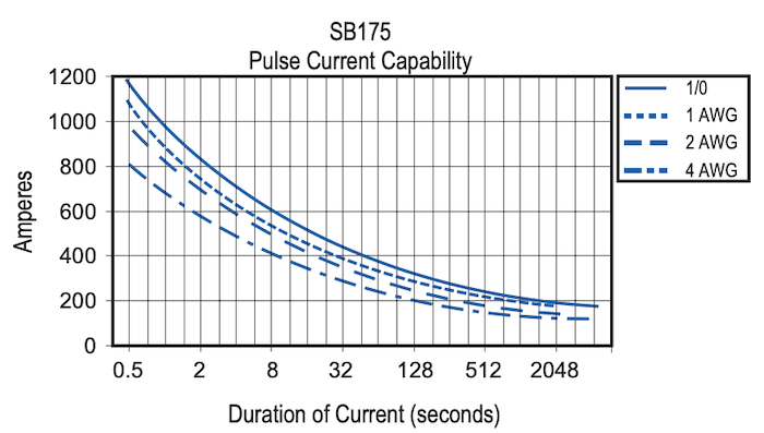
So if you use a smaller cable the limitation is apparently the cable itself, not the connector/terminal. That doesn't mean it's zero but that we have more to worry about
in my opinion making a potential compromise on using 2 AWG rather than 1/0 AWG over the whole circuit rather than just using an SB175 in this application.
FWIW I think the original sizes supplied with winches in these conditions is fine typically. If use larger like 1/0 that's better and you should. But remember that you also have to size up the cables after the control box for this to be a net benefit. If you run 1/0 to the box but leave 4 AWG for the motor leads after then you're still making a compromise overall.

