I am thinking along the same lines as Martin.. could you put a smaller pulley on the PS pump? that would make it pump a little more, but.. so what?
-
 COLOYOTA EXPO: Vote for your favorite shirt color.
Click here to see the options and place your vote.
You are using an out of date browser. It may not display this or other websites correctly.
You should upgrade or use an alternative browser.
You should upgrade or use an alternative browser.
The Projects
- Thread starter subzali
- Start date
kurtnkegger
Rising Sun Member
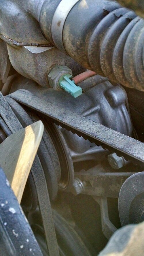
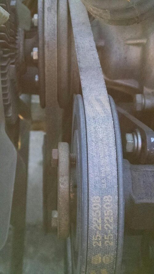
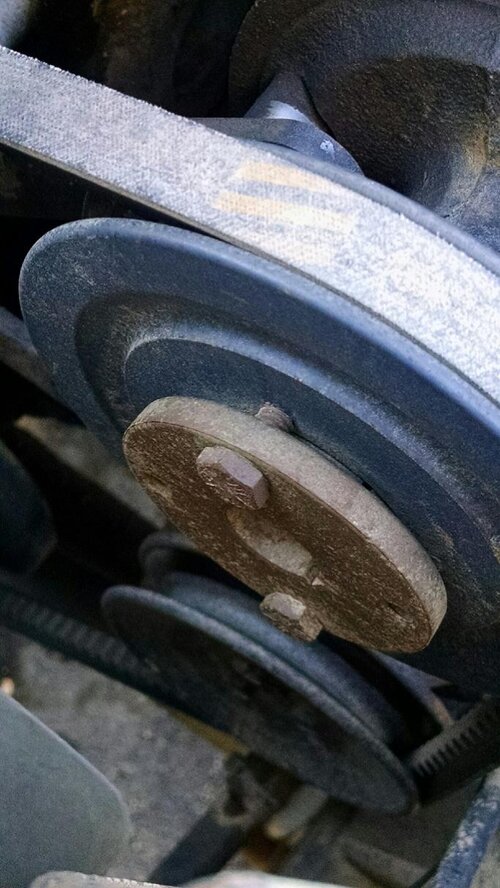
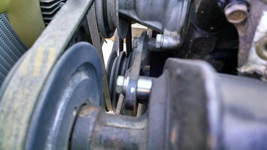
Matt, I put a pulley on my pump that I got from Grainger. My pump sits at a bit of an angle, and the section of belt that heads down to the air pump is very close to the radiator support rod. Maybe the combination of the different pulley, and maybe a longer belt puts the belt position lower on the top side? Anyway, here are a few pictures of my set-up.
Attachments
Is the pulley on the Saginaw bigger than an FJ60 or mini truck pump?
I am thinking along the same lines as Martin.. could you put a smaller pulley on the PS pump? that would make it pump a little more, but.. so what?
I finally pulled my boxes of power steering parts open last night and took some measurements. The OEM FJ60 pulley is 5 5/8” diameter. The Saginaw pulley is 5 ¾” diameter. The Volvo pulley I am currently running is just a hair over 6” diameter. So this could be definitely making a difference in clearance here. So I’m going to have to do some thinking on solutions here, but in the meantime I’m going to run it as-is and realize I can’t have everything perfect (remember the reason I went to the Volvo pulley was to get a wider belt on the Saginaw pump).Matt, I put a pulley on my pump that I got from Grainger. My pump sits at a bit of an angle, and the section of belt that heads down to the air pump is very close to the radiator support rod. Maybe the combination of the different pulley, and maybe a longer belt puts the belt position lower on the top side? Anyway, here are a few pictures of my set-up.
Last edited:
treerootCO
Rising Sun Member
- Joined
- Aug 22, 2005
- Messages
- 5,431
I think that would negatively affect the heater performance.
RicardoJM
Hard Core 4+
i Think That Would Negatively Affect The Heater Performance.
+1 :d
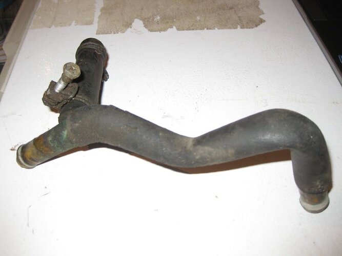
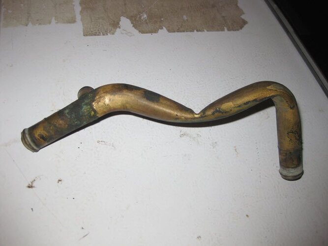
It's only a minor flow restriction.
kurtnkegger
Rising Sun Member
It's only a minor flow restriction.
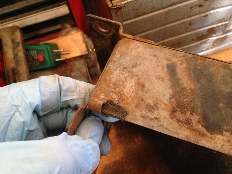
+1...I think that could be buffed out

Yikes. How do you think that happened?
It's somewhat unprotected in the configuration in which it's mounted to the heater.
Also did some other stuff last night.
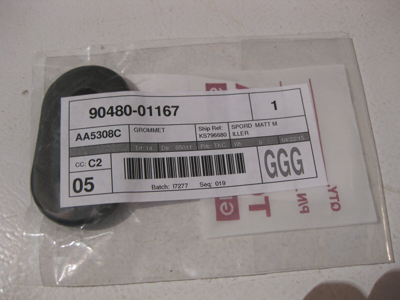
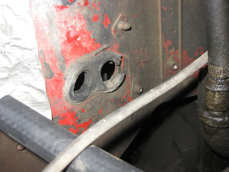
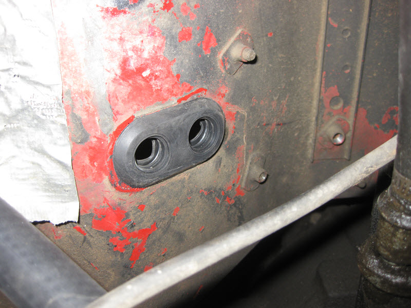
Replaced the heater hose grommet in the firewall:
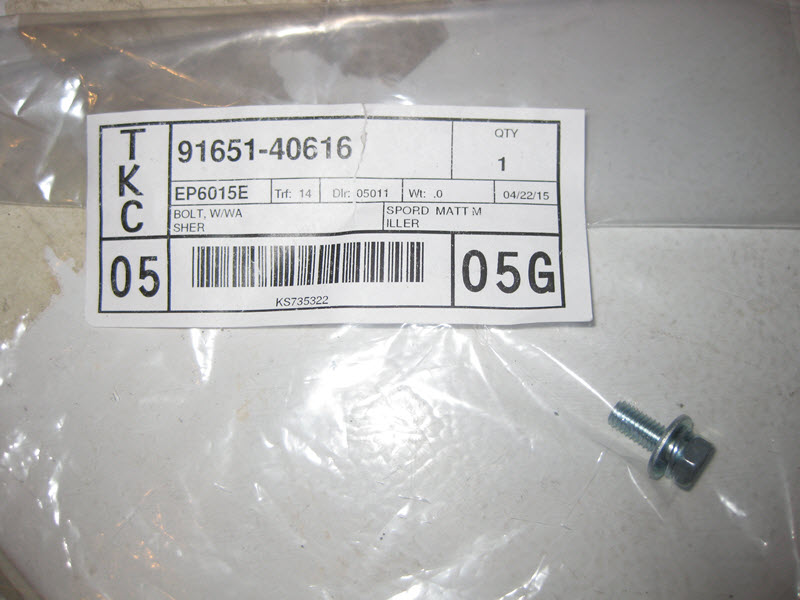
Also replaced the 7 fasteners for the fuel tank cover:
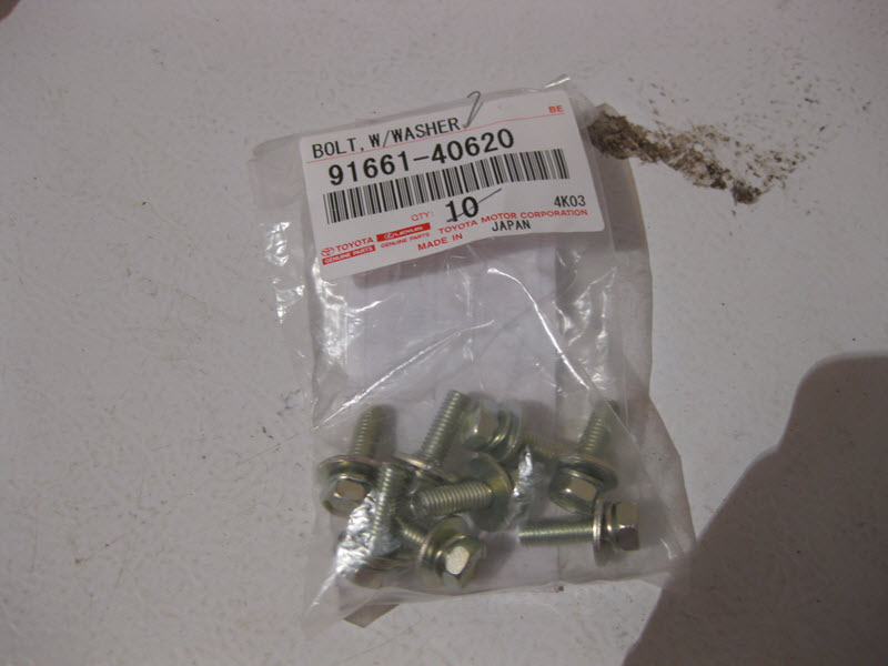
Old vs. new
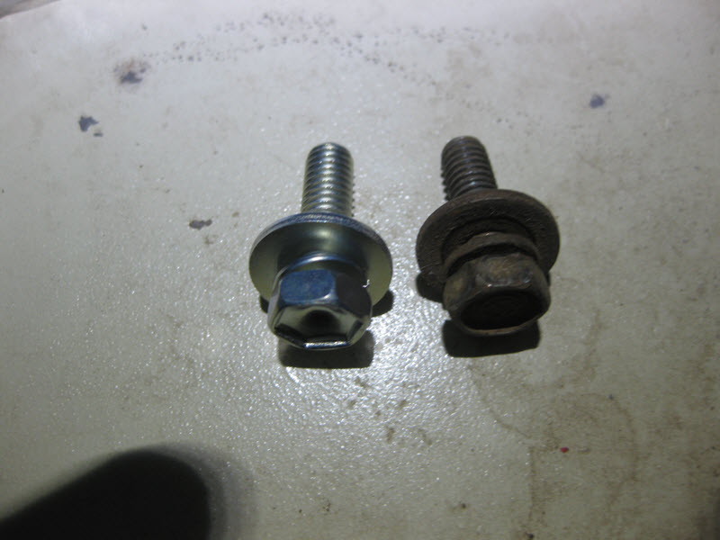
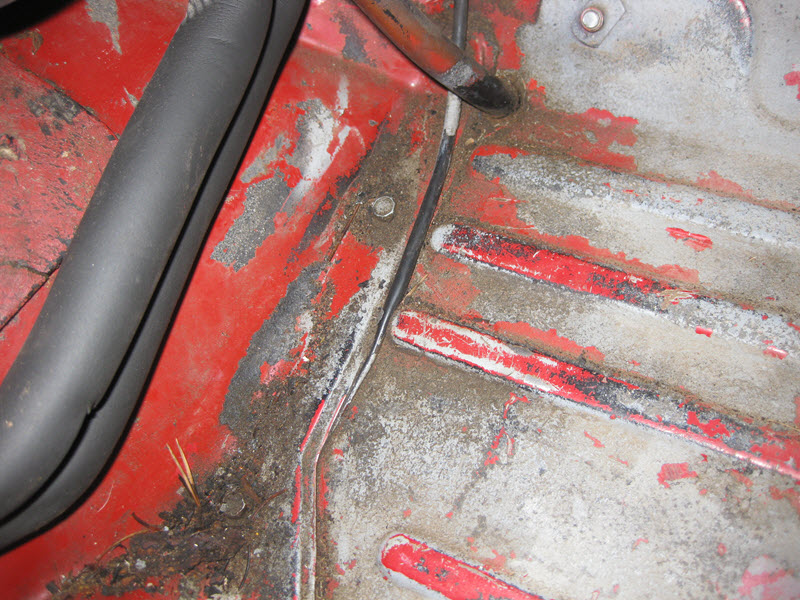
Also replaced the little fastener that holds the heater hose clamp on the floor - this hole was plugged with junk so I had to clean it out first. All new fasteners going in with anti-sieze.
Little gem hiding there between the seats...
QUESTIONS
It seems like this forward most heater hose clamp is different than all the others, does anybody else have something similar?
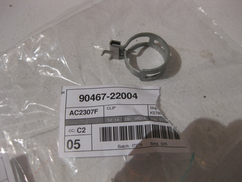
This is the one I have in place there now, the original one was a lot different.
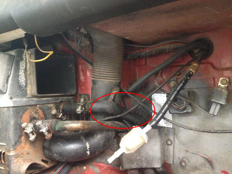
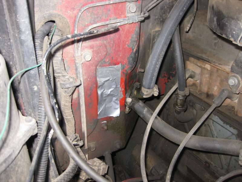
What are these two holes in the firewall for? I don't suppose this vehicle ever had A/C, but they don't really look like they were cut by someone in their garage.
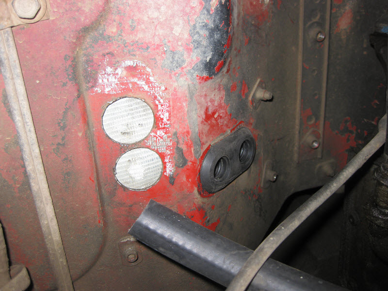
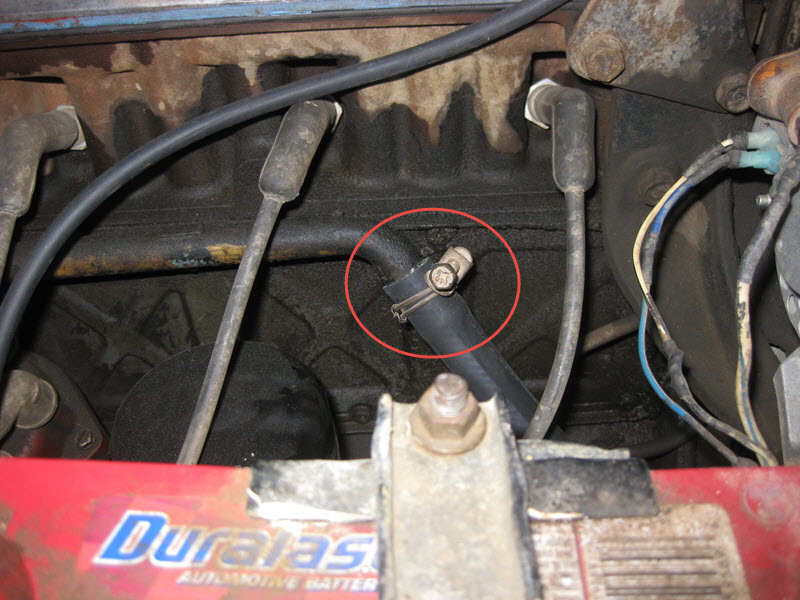
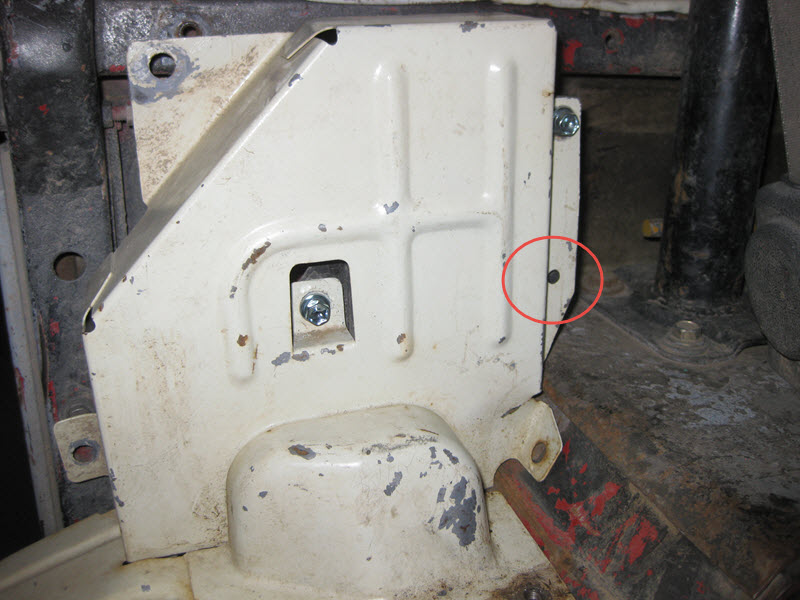
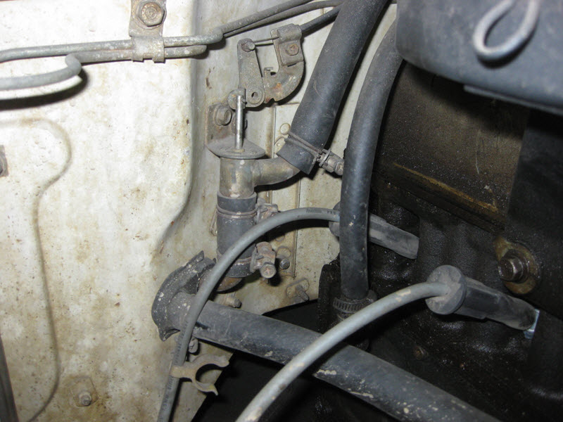
What is this hole for? Does it contain a bolt and nut to hold the vapor separator?
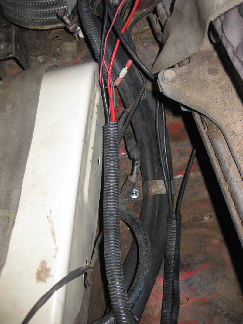
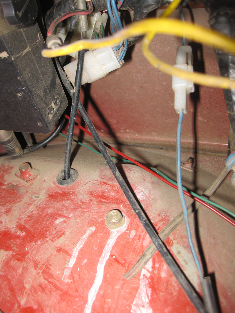
Does the power wire for the rear heater run under the tranny tunnel like so? I need to check the wiring diagram, this is a LB wire (light blue with black stripe). It pops back out from under the tranny tunnel next to the fuel tank cover.
And here's a bad pic of it running up and connecting to the harness behind the dashboard:
Now to compare firewalls:
Another angle:
This is Sascha's '77:
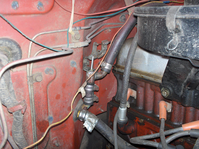
And this is Romer's/nakman's old '77:
Here is a picture from CCOT's website of their A/C lines through the firewall:
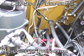
I guess those holes are not supposed to be there.
Another angle:
This is Sascha's '77:
And this is Romer's/nakman's old '77:
Here is a picture from CCOT's website of their A/C lines through the firewall:
I guess those holes are not supposed to be there.
Last edited:
Rezarf
Hard Core 4+
I'd say those holes aren't factory.
rover67
Rising Sun Member
My '82 has those holes. I think it was for AC at some point.
My '82 has those holes. I think it was for AC at some point.
I'd be interested in seeing a picture of you could post one.
Since I had the cooling system drained, I decided to finally dive into my front heater rebuild project.
Have never been fully satisfied with the heater operation. Broke it the day the 40 was purchased and I was driving home from Grand Junction in a snowstorm in January. It was stuck on vent so I essentially had no heat, and to top it off the fuel vapor smell was so bad in the cab that I had to leave my driver window cracked the whole way to try and ventiliate the area. That cold drive was my introduction to FJ40s, I fixed the heater when I got home and figured out what the problem was, and the fun has never stopped. But I digress…
I followed Zepp’s writeup early on:
http://rzeppa.org/tech/staywarm.htm
I have also followed Mark Whatley’s advice on a couple occasions and have done the muriatic acid treatment to my heater core.
In 2008 I did some work on my doors and replaced the weatherstripping and felts to try to seal things up better and reduce rattles. Somewhat effective.
In December of 2011 we did that crazy night run up Argentine, and since it was hovering around 0 my heater was getting a workout. But what I also was noticing was that the heater duct was leaking, so that almost as much cold air was being injected into the cabin as hot air from the heater.
A year or so ago I bit the bullet and bought Metric TLC’s (Shane) heater and heater duct rebuild kits. Was waiting for an opportunity to drain the cooling system, and since one thing has led to another with this re-smog project I decided it was time.
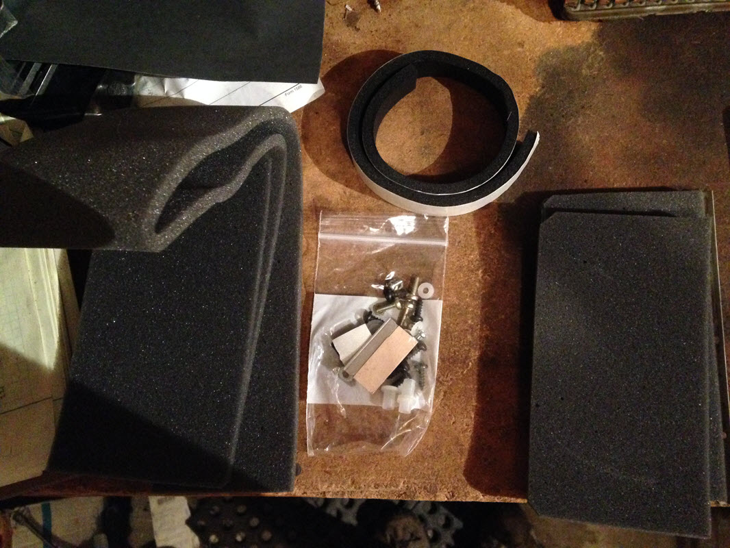
Just in case Metric TLC doesn’t end up coming back around as far as Shane’s health or whatever else is going on, I figured I would document what is in the kit so someone else can piece their own together if they please.
Front Heater rebuild 1974-1977:
I noticed that he does not replace the nylon shoulder bushings that are part of the OEM setup with an exact replacement part. I’m going to try to find them on McMaster or someplace. The original flanged shoulder spacers are:
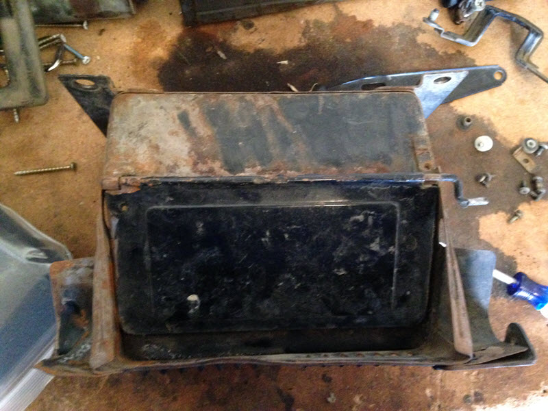
First step was getting my heater out, disassembling and cleaning it up. I noticed a few things upon disassembly. First up is that my heater core is very clean because I’ve cleaned it on several occasions. Notice also the little pieces of foam on both sides of this retainer plate:
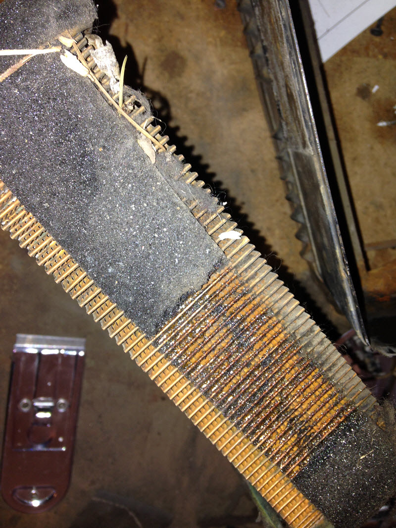
Next is that animals have been digging up the foam on the blending door:
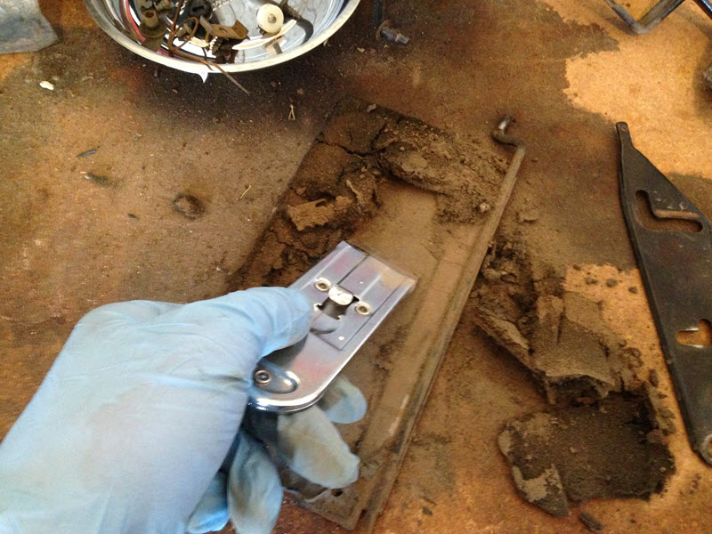
Unfortunately the old Grateful Dead sticker had to go. As I disassembled it I couldn’t get the bottom door off because the bottom sides had been bent in to create a flange. Seen here:
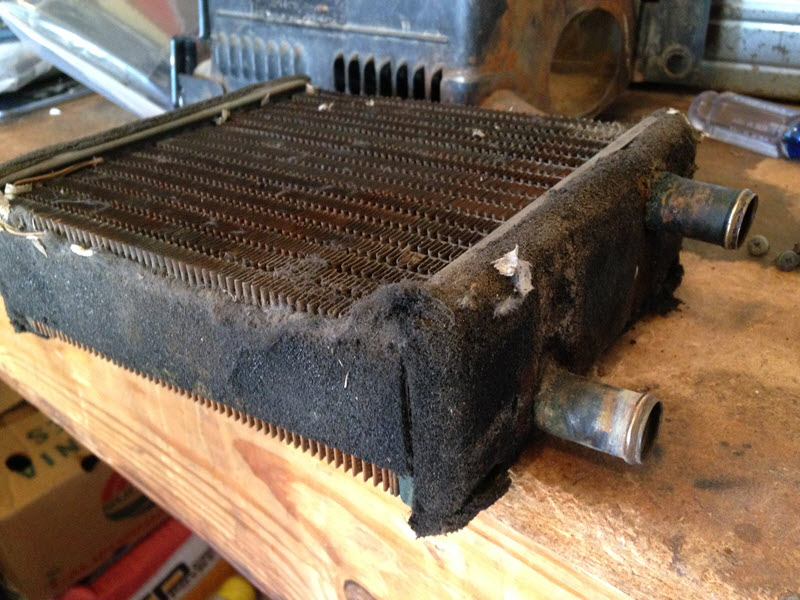
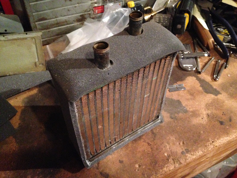
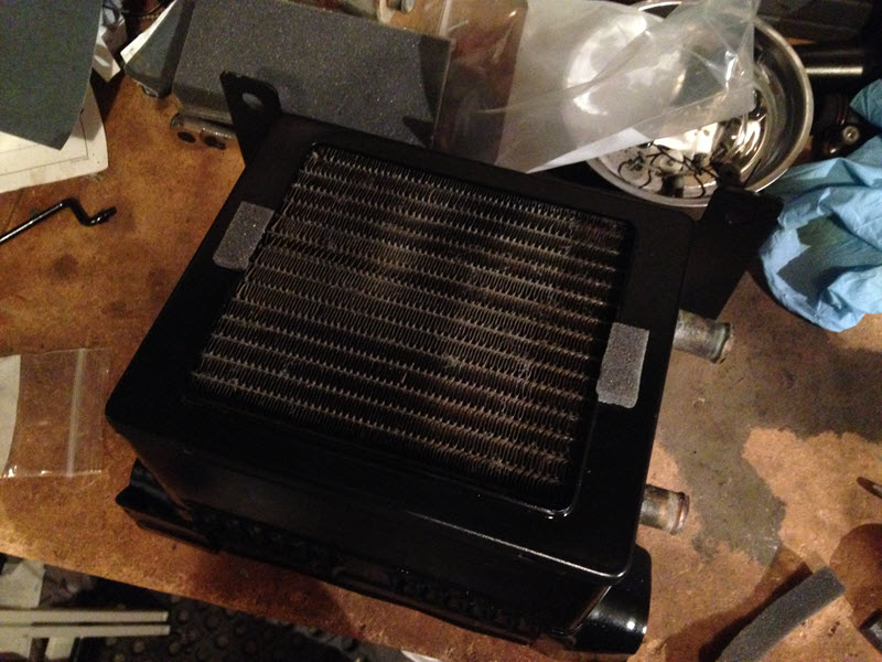
I carefully straightened it out and I was good to go. Also had to remove some of the old foam, some of which was more or less gone anyway. Here is a picture of the heater core with the sealing foam around it. The foam is very deteriorated after all these years:
Scraping off the old foam:
Stripped the foam off the heater core:
There’s a little piece of foam here on the defroster door, don’t forget this when putting it back together:
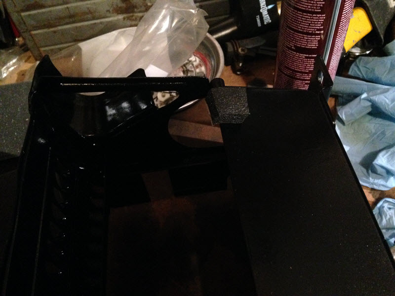
I went around and sanded down the rust and other marks until I was using 600 grit sandpaper, and went ahead and threw primer and gloss black on the heater shell and other painted parts. Tried to be patient and go in several light coats so as not to create any runs or sags and actually did pretty good. I’m usually so impatient I don’t get that part right. I also usually don’t have the patience to wait for the paint to dry and muck stuff up because I put it back together too soon. In this case I’ve been noticing that after 2-3 days the paint is much harder and hopefully more durable when reassembly time comes.
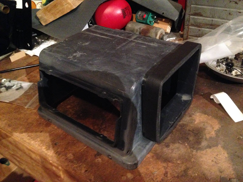
As I was waiting for paint to dry, I busied myself with other tasks. The rincess was gone one night so I used the opportunity to wash my heater duct and other plastic bits in the bathtub
  Made quite a mess of the bath water, but now my ducts are squeaky clean. I sanded them down with the 600 grit, and a bunch of the elbow grease time was spent getting the spackle texture paint overspray from previous owner days off of the ductwork.
The last little item before reassembly was to fix the upper door spring. It was bent in too many places too many times, so I heated it up to relieve the stress and got it straightened out and pointing the right direction.
Metric TLC has rebuild instructions here:
http://metrictlc.com/Front_Heater_Restoration.html
Here are some pictures of my reassembly process:
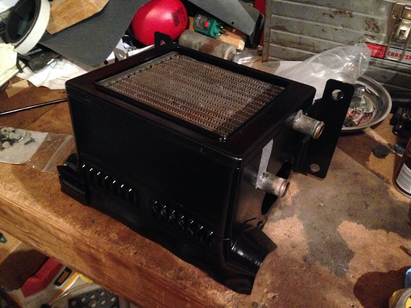
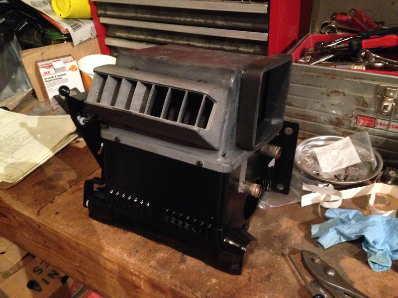
The actuator lever to put it on defrost is really tight now, so I think I have too much foam or too much foam in the wrong place so things aren't lining up quite perfectly. Still need to adjust that.
Next up was the blower motor. Toyota makes it convenient to remove and put back on, as the bottom of the housing is slotted to sit on two lower bolts on the firewall. So you only have to completely remove the two upper bolts.
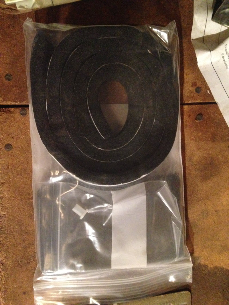
Heater Duct and Blower rebuild parts:
Nasty
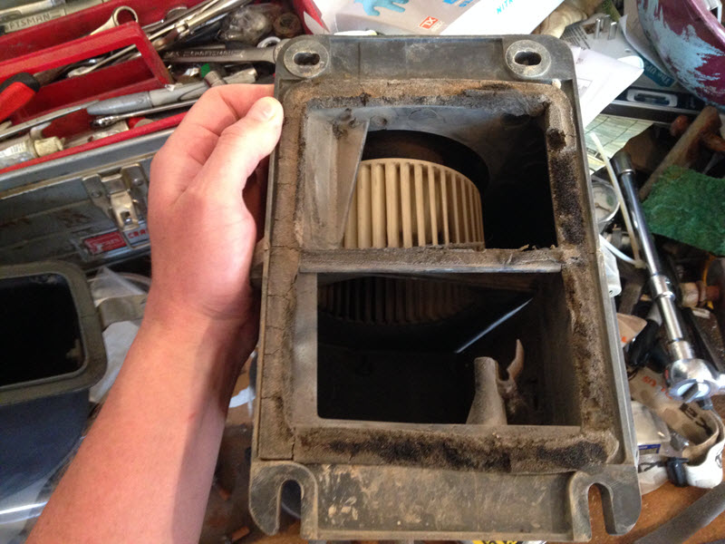
Some guys clean the blower out and make it squeaky clean, for me this project is already overdue to be wrapped up so I just put new foam on it and called it good. Without a cabin air filter I don't really see the point anyway.
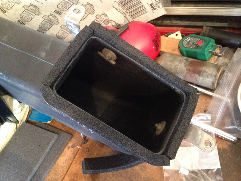
The recirculation door is supposed to have foam on both sides, the foam on mine was gone from either one or both sides, I can’t remember now. So this needed to be done.
New foam
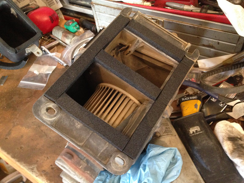
Shane didn’t provide enough length of foam to seal the duct on both sides of the firewall, so I had to cut one of the foam strips lengthwise in order to have enough to wrap around the duct:
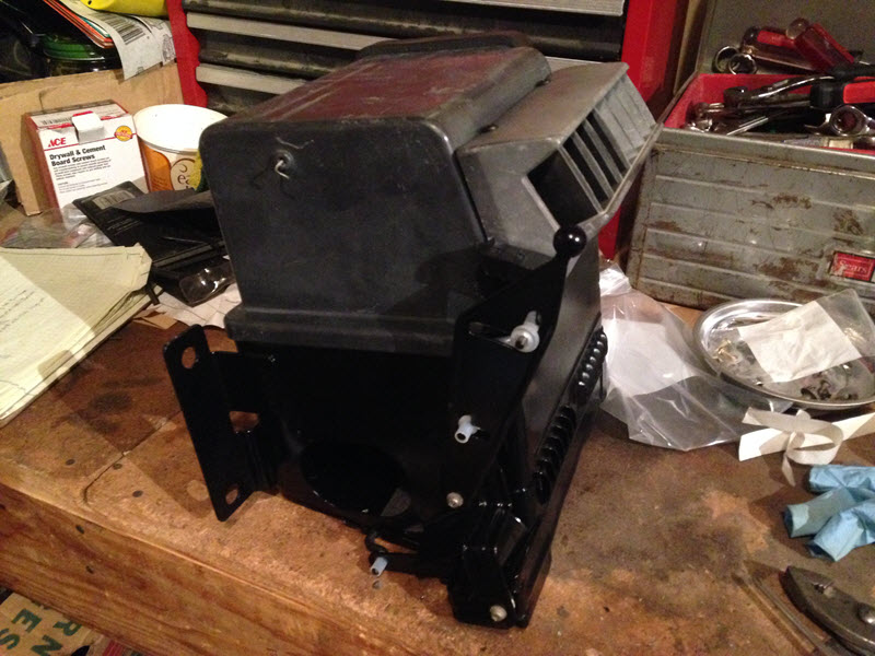
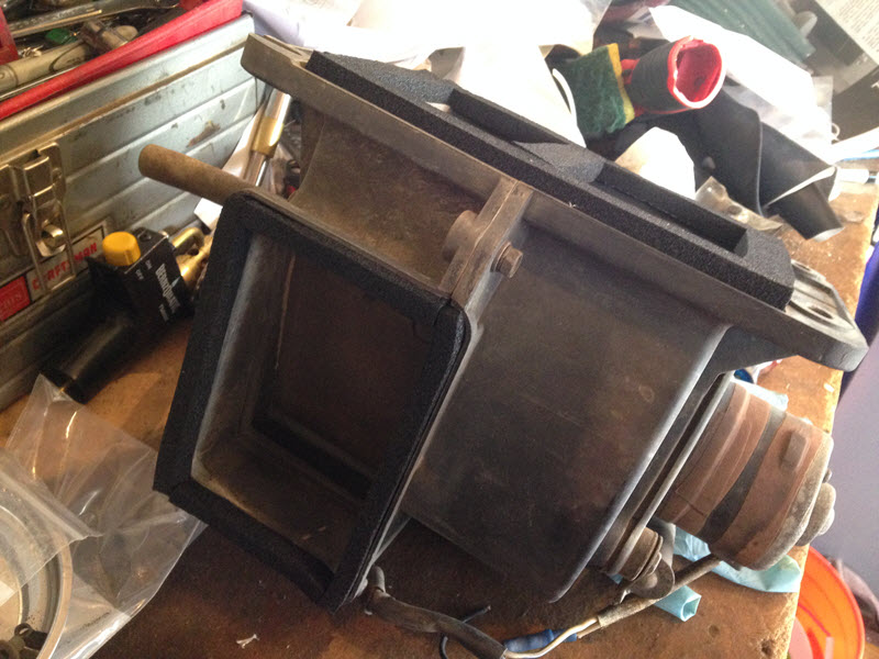
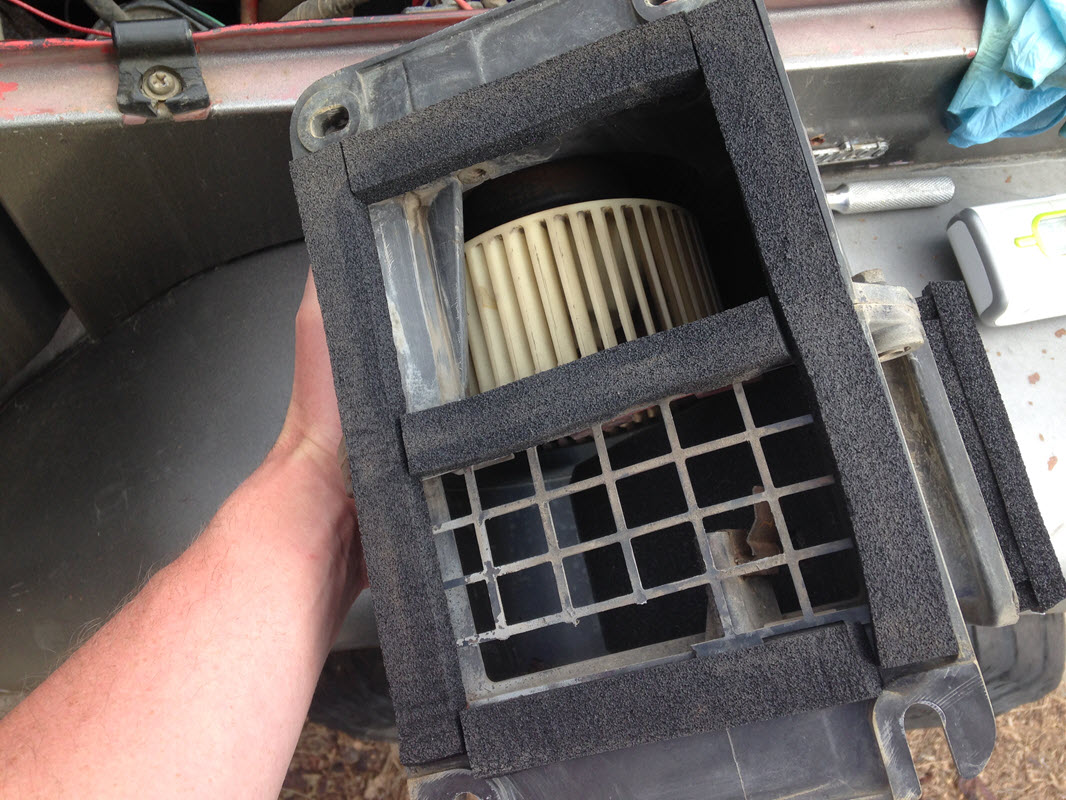
It seemed to make sense to me to put this grate inside the blower motor, but according to antFJ on MUD the grate clips into the firewall. This actually makes the feeding of the fresh air control cable much easier now that I think about it.
So don’t do it like this: here you can also see the slots on the bottom of the motor housing for the blower to sit on while you thread the two upper bolts.
So now that that's done, on to the next thing!
Have never been fully satisfied with the heater operation. Broke it the day the 40 was purchased and I was driving home from Grand Junction in a snowstorm in January. It was stuck on vent so I essentially had no heat, and to top it off the fuel vapor smell was so bad in the cab that I had to leave my driver window cracked the whole way to try and ventiliate the area. That cold drive was my introduction to FJ40s, I fixed the heater when I got home and figured out what the problem was, and the fun has never stopped. But I digress…
I followed Zepp’s writeup early on:
http://rzeppa.org/tech/staywarm.htm
I have also followed Mark Whatley’s advice on a couple occasions and have done the muriatic acid treatment to my heater core.
In 2008 I did some work on my doors and replaced the weatherstripping and felts to try to seal things up better and reduce rattles. Somewhat effective.
In December of 2011 we did that crazy night run up Argentine, and since it was hovering around 0 my heater was getting a workout. But what I also was noticing was that the heater duct was leaking, so that almost as much cold air was being injected into the cabin as hot air from the heater.
A year or so ago I bit the bullet and bought Metric TLC’s (Shane) heater and heater duct rebuild kits. Was waiting for an opportunity to drain the cooling system, and since one thing has led to another with this re-smog project I decided it was time.
Just in case Metric TLC doesn’t end up coming back around as far as Shane’s health or whatever else is going on, I figured I would document what is in the kit so someone else can piece their own together if they please.
Front Heater rebuild 1974-1977:
- Qty 2 open cell foam pieces 3-3/8” x 6-3/8” x ¼” thk. with 2 corners trimmed
- Qty 1 open cell foam piece 7-½” x 3-7/8” x ¼” thk. with 2 corners trimmed
- Qty 1 closed cell foam piece with self-adhesive ¾” x ¼” x 19-5/8”
- Qty 1 open cell foam piece 3” x ¼” x 31”
- Qty 1 closed cell foam piece with self-adhesive ¾” x ¾” x 3/8”
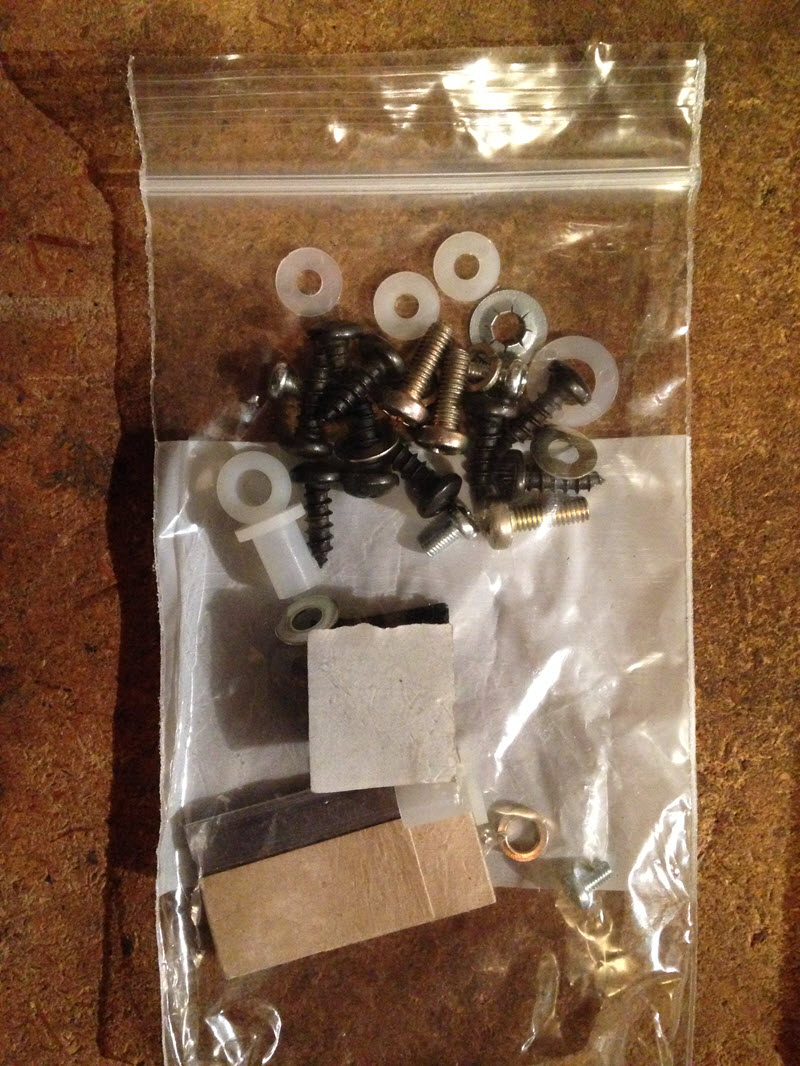
- Hardware kit
I noticed that he does not replace the nylon shoulder bushings that are part of the OEM setup with an exact replacement part. I’m going to try to find them on McMaster or someplace. The original flanged shoulder spacers are:
- 2x 0.26 shoulder OD, 0.183” shoulder ID, 0.545” flange OD, 0.04” flange thickness, and 0.354” OAL
- 2x 0.535” flange OD, 0.165” shoulder ID, 0.305” shoulder OD, 0.192” flange thickness, 0.257” OAL
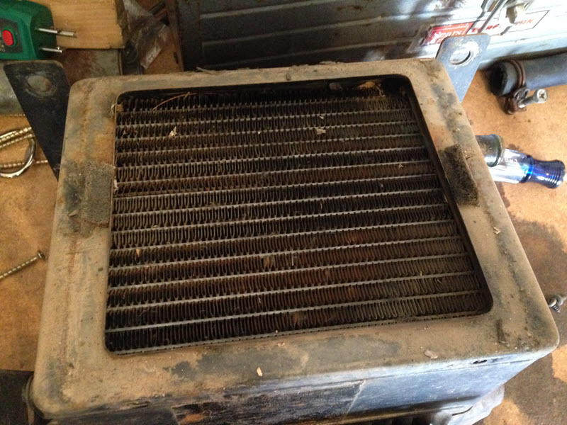
First step was getting my heater out, disassembling and cleaning it up. I noticed a few things upon disassembly. First up is that my heater core is very clean because I’ve cleaned it on several occasions. Notice also the little pieces of foam on both sides of this retainer plate:
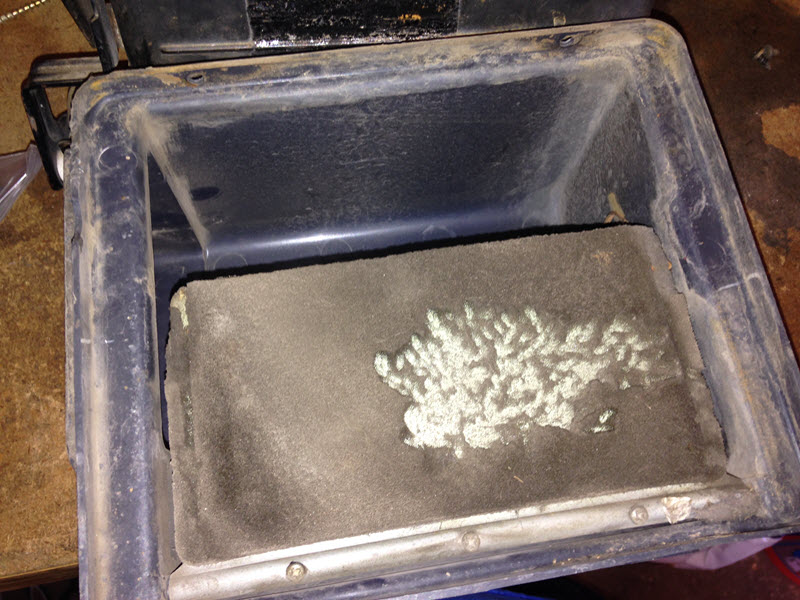
Next is that animals have been digging up the foam on the blending door:
Unfortunately the old Grateful Dead sticker had to go. As I disassembled it I couldn’t get the bottom door off because the bottom sides had been bent in to create a flange. Seen here:
I carefully straightened it out and I was good to go. Also had to remove some of the old foam, some of which was more or less gone anyway. Here is a picture of the heater core with the sealing foam around it. The foam is very deteriorated after all these years:
Scraping off the old foam:
Stripped the foam off the heater core:
There’s a little piece of foam here on the defroster door, don’t forget this when putting it back together:
I went around and sanded down the rust and other marks until I was using 600 grit sandpaper, and went ahead and threw primer and gloss black on the heater shell and other painted parts. Tried to be patient and go in several light coats so as not to create any runs or sags and actually did pretty good. I’m usually so impatient I don’t get that part right. I also usually don’t have the patience to wait for the paint to dry and muck stuff up because I put it back together too soon. In this case I’ve been noticing that after 2-3 days the paint is much harder and hopefully more durable when reassembly time comes.
As I was waiting for paint to dry, I busied myself with other tasks. The
rincess was gone one night so I used the opportunity to wash my heater duct and other plastic bits in the bathtub Made quite a mess of the bath water, but now my ducts are squeaky clean. I sanded them down with the 600 grit, and a bunch of the elbow grease time was spent getting the spackle texture paint overspray from previous owner days off of the ductwork.The last little item before reassembly was to fix the upper door spring. It was bent in too many places too many times, so I heated it up to relieve the stress and got it straightened out and pointing the right direction.
Metric TLC has rebuild instructions here:
http://metrictlc.com/Front_Heater_Restoration.html
Here are some pictures of my reassembly process:
The actuator lever to put it on defrost is really tight now, so I think I have too much foam or too much foam in the wrong place so things aren't lining up quite perfectly. Still need to adjust that.
Next up was the blower motor. Toyota makes it convenient to remove and put back on, as the bottom of the housing is slotted to sit on two lower bolts on the firewall. So you only have to completely remove the two upper bolts.
Heater Duct and Blower rebuild parts:
- Qty 2 open cell foam pieces 3” x 5-1/4” x ¼” thk.
- Qty 1 closed cell foam piece with self-adhesive strip ¾” x 3/8” x 53” (this should be longer by maybe 12" to have enough to seal the duct on both sides of the firewall)
- Qty 1 nylon long barrel flanged shoulder spacer for a No. 10 screw size (0.375” shoulder length, 0.399” flange OD, 0.063” flange thickness, 0.260” shoulder OD, 0.200” shoulder ID), McMaster part number 91145A157 for a package of 100: http://www.mcmaster.com/#91145a157/=wdla7u
Nasty
Some guys clean the blower out and make it squeaky clean, for me this project is already overdue to be wrapped up so I just put new foam on it and called it good. Without a cabin air filter I don't really see the point anyway.
The recirculation door is supposed to have foam on both sides, the foam on mine was gone from either one or both sides, I can’t remember now. So this needed to be done.
New foam
Shane didn’t provide enough length of foam to seal the duct on both sides of the firewall, so I had to cut one of the foam strips lengthwise in order to have enough to wrap around the duct:
It seemed to make sense to me to put this grate inside the blower motor, but according to antFJ on MUD the grate clips into the firewall. This actually makes the feeding of the fresh air control cable much easier now that I think about it.
So don’t do it like this: here you can also see the slots on the bottom of the motor housing for the blower to sit on while you thread the two upper bolts.
So now that that's done, on to the next thing!
Last edited:

CardinalFJ60
Rising Sun Member
great writeup!
I'll be diving into this sometime soon. thanks for the great info.
I'll be diving into this sometime soon. thanks for the great info.
Rezarf
Hard Core 4+
Looking good Matt! I'll up this info later.
rover67
Rising Sun Member

That's on my truck