Against all my better engineering judgment ("not knowing 'enough' information") I have begun my long sought-after power steering conversion. I liked the premise of TJ's FJ60 power steering and after seeing Mark Whatley's article in July/August 2003 TT on it as well I wanted to try it with my own tweaks. A couple other guys in the club have done it as well so after many hours of talking and figuring I felt I had enough to actually pull the trigger and go with it. Of course there were some issues that came up a couple days ago that attempted to halt it again, but I was already steaming up to get 'er done!
So here's the breakdown:
-FJ40 steering wheel
-FJ55 steering column (splined at firewall vs. rag joint) v2.0 - FJ40 steering column w/ rag joint cut off and "double-D" ground onto end of shaft
-U-joints from FJ55 intermediate shaft to mate to bottom of steering column at firewall v2.0 - Cruiser Outfitters steering column bearing installed in steering column
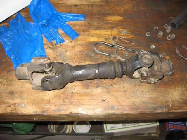
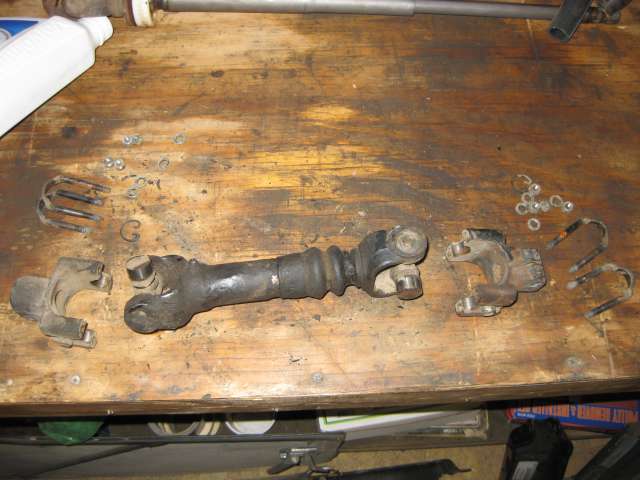
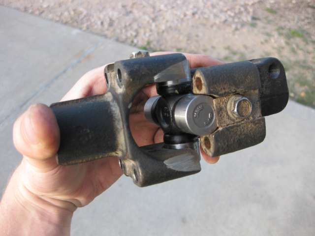
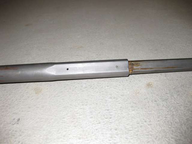
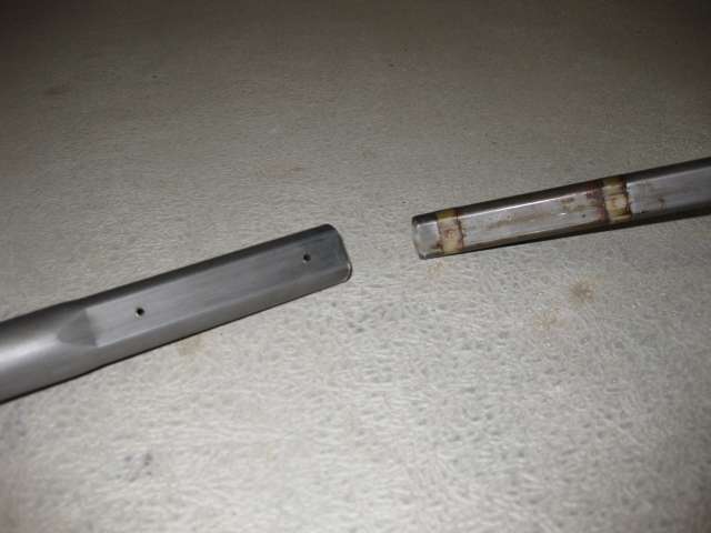
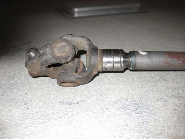
-FJ60 steering column, taken apart and used to mate up with FJ55 column to become the new intermediate shaft. Since the 60 column is collapsible, and is held in place with a couple plastic pins, you can punch out the plastic pins and all the sudden you have yourself a slip joint to allow the frame to flex different than the body. v2.0 - Borgeson intermediate shaft w/ slip joint. 3/4" Double-D on column/firewall end, 11/16" - 36 spline on gearbox end
-FJ60 steering box
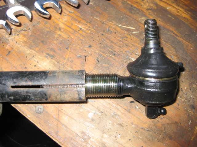
-LHD J7 drag link end
-LHD J7 drag link tube
-FJ40 driver's side TRE v2.0 - J6 drag link end
-v2.0 - stock FJ40 tie rod end with drag link connection reamed out to fit abovementioned J6 drag link end (reaming done by Cruiser Outfitters)
-FJ40 tie rods (small taper)
-FJ40 knuckles (small pattern)
-Ford F-250 shock towers (not straightened)
-GM Saginaw power steering pump
-JT Outfitters bracket,pulley, and high pressure hose EDIT: Use a Volvo 240 pump/pulley setup, see page 9. It fits a wide belt instead of the JTO solution which is for a narrow belt.
-FJ60 power steering cooler, rebent to mount in my FJ40.
On v1.0 I had 40/55/60/70/GM steering, for v2.0 I have 40/Datsun/Borgeson/60/70/GM steering")
I liked the FJ60 box because I saw it could work, for some reason I never really liked the idea of full Saginaw conversions, and I didn't want minitruck because it keeps all of the relay rods etc. which I consider to be "unnecessary" and just add more places where slop can develop. Currently my steering has quite the wander, mostly because of my steering box (I put on new TREs and rebuilt the Center Arm before I finally saw the steering box itself had slop) and this is my solution.
Here's some questions I asked on IH8MUD about the differences between Saginaw boxes and FJ60 boxes
I wanted to use an FJ60 power steering pump, but the Saginaw has more boost I understand and since my block wasn't tapped for the stock power steering pump bracket, I figured I would go with the JT Outfitters bracket because I could fit either the stock air pump or a Sanden air pump underneath the power steering pump and have factory emissions or OBA.
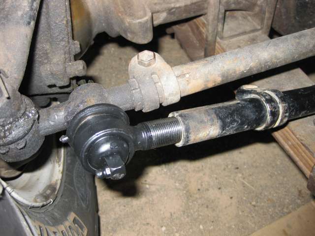
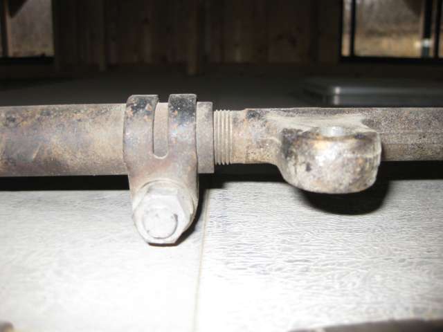
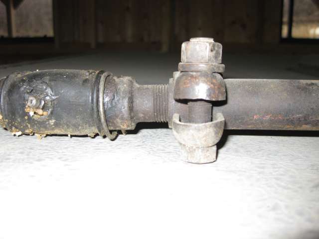
The beauty, I think, of what I'm going to try and do here, is that I'm going to use a modified Land Cruiser drag link. No custom drag link (though if I were running heavier duty TREs etc. I would go that way for sure), and no sleeving/cutting and welding a drag link together (I definitely don't want this to fail on or off road). After doing some measuring and figuring I *should* be able to use a LHD J7 rebuildable drag link end at the pitman arm, a J7 drag link tube, and the driver's side TRE from an FJ40. That way the threads, size, and taper should mate the J7 drag link tube to the FJ40 tie rod. More details to follow on that.
I'm also doing F-250 shock towers to allow a longer travel shock absorber, since I need new shocks anyway
Previous Work (besides all the figuring, talking, sketching, and daydreaming about FJ60 power steering
Tools needed
1. Pulley installer/remover kit ($12 at Harbor Freight)
2. Various box end wrenches/ratchet/sockets
3. Vice
4. Torque wrench (up to 90 ft-lbs for the head bolts)
(two sets of hands helps, but not necessary)
(Note: If you're using the JTO pulley (which I would not recommend, there's a better solution), it goes on with the grooved part of the hub facing out; the clamshell of the puller has to be able to attach to it if you ever want to get it off, plus that's the only way it will align properly and not interfere with the fan)
The JTO-style pulley needs to be installed something like this (stolen from Treeroot):
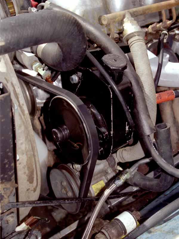
I bought a Saginaw pump and pulley from JT Outfitters along with the bracket to mount it to the front two exposed head bolts. I figured I could at least get that figured out and mounted to the truck, to make sure there were no surprises there. Well lo and behold there were some surprises. I put the pulley on backwards and thus could not get it off with the puller (there is a place on the hub for a clamshell to catch and pull the pulley off, but if it's on backwards it won't work). So I had to order a new pulley, cut a pie-shaped wedge out of the old one, then chisel it until it slid off. Then install the new pulley and mount it to the head bolts. Mounting it to the truck was pretty easy, once the pulley was on correctly EDIT: should have just gone with the Volvo pulley in the first place, would have been a lot easier and less $$ shelled out in the long run.
I also spent 4 hours last week cutting/straightening and welding the Ford shock towers (and bs-ing with Ige). I did this because I wanted to keep from cutting the fenders. But they have to be cut anyway for the steering box, and mine are rusty anyway, so I don't know why I'm making a big deal about it. I think there's going to be interference with the steering box as well, so I was probably jumping the gun a bit to do that, but I can always reverse those kinds of things right? EDIT: should have not straightened the shock towers, shoulda just left them as-is
Day 1 (or "It's amazing what you can do with an angle grinder and a couple of hours of your time): April 26, 2009 - 8 hours
Tools needed
1. Angle Grinder with cutoff wheel and grinding wheel
2. Various box end wrenches (loving my stubby Gear Wrenches)/ratchet/sockets
3. Various screwdrivers
4. C-clip pliers
5. Small Sledge/mallet
6. TRE puller (finally bought one - NOT a pickle fork but a puller - $25 at NAPA)
7. C clamps to clamp p/s box to frame for mockup
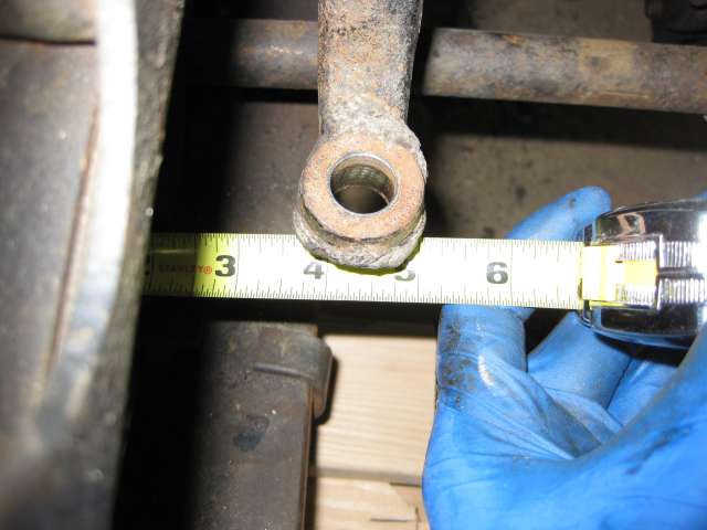
8. Tape measure
(Note: PB Blaster helps in the rusty bolt arena of getting stuff off - I broke two today)
1. I removed the doors and hard top just 'cause.
2. I removed the shocks. I don't know how old they are, they could be OEM, at any rate they don't work all that great. Since it's just past 4 years I've owned this truck I figure I'd better replace them
3. I removed the Center Arm and detached it from the steering stabilizer, drag link and relay rod. If anybody needs a good Center Arm let me know, I rebuilt it a couple years ago and it's in pretty good shape. I actually think I have a couple of these now.
4. I removed the apron and fender to give myself some workspace and put my truck up on blocks so I could take the tire off.
5. I removed the driver side shock tower. At first I tried to be nice, I thought I could buzz the rivets down then punch them into the frame and pull off the shock tower. Not so today, those rivets are VERY TIGHT in the frame. So I switched to the cutoff wheel and cut the corners off then beat it off with a small sledge. That was fun (at this point I'm committed to a new shock tower arrangement)
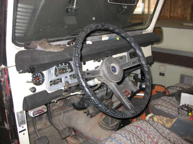
6. I removed the steering column and rag joint. It took me a while to figure out that there was a c-clip holding the lock cylinder on the shaft, once I found it it was only a couple minutes to slide that off and slide the inner steering column through the firewall.
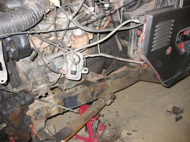
7. I removed the steering box. First I scraped off the gunk and unbolted the box from the pedestal then I cut the pedestal (see I can learn too! ) then beat it off too. (At this point I'm committed to new steering)
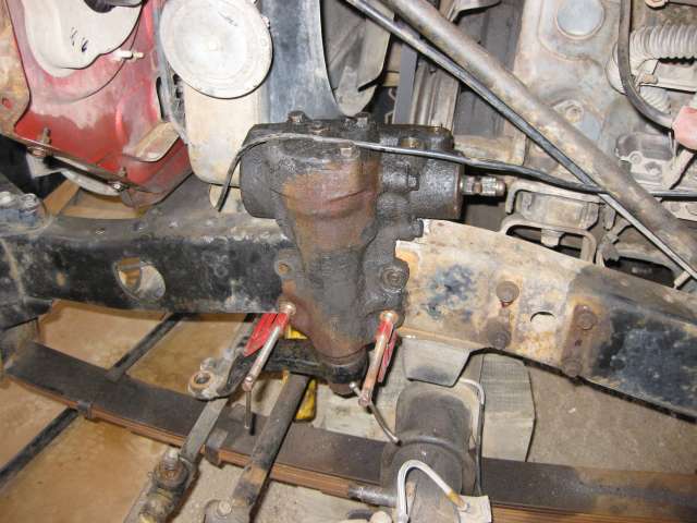
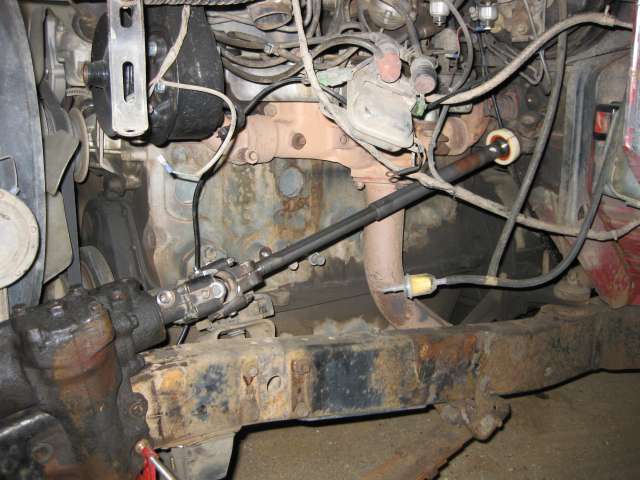
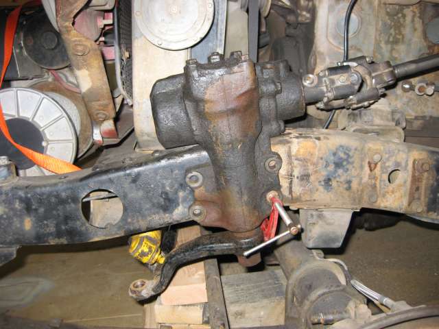
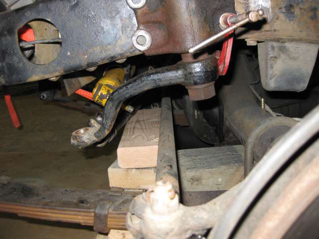
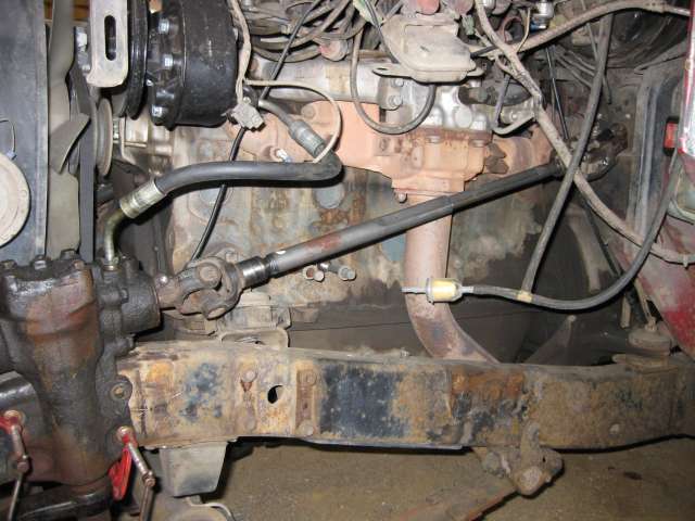
8. Once I had the frame cleared, I mocked up the FJ60 steering box with a couple clamps to get it in the approximate position. I then took some measurements to the tie rod to see if my J7 solution to the drag link will work. I think it will, so I will order the couple parts I lack on that end and get that mocked up in a couple weeks.
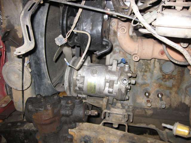
9. I mocked up the Sanden OBA pump that Neil Quigley let me borrow. I'm going to have to convince him to sell it to me I think it will be a good use of space and will give me the functionality I want. I can run it off the p/s pump belt, and there should be sufficient wrap for both to work well.
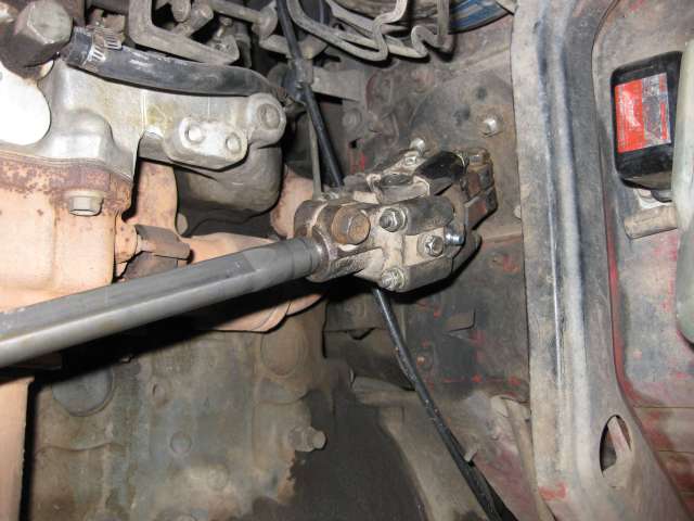
10. I mocked up the intermediate shafts, just trying to see what's going to have to happen. I need to recombine some u-joints and then I should be able to set where the steering box will sit on the frame. I'm hoping there will be enough room to fit the F-250 shock tower behind it without interfering with the fender support. If I get really lucky I won't have to relocate the shock tab on the axle.
11. Started making a list of all the things I'm going to have to figure out before I'm through with all this
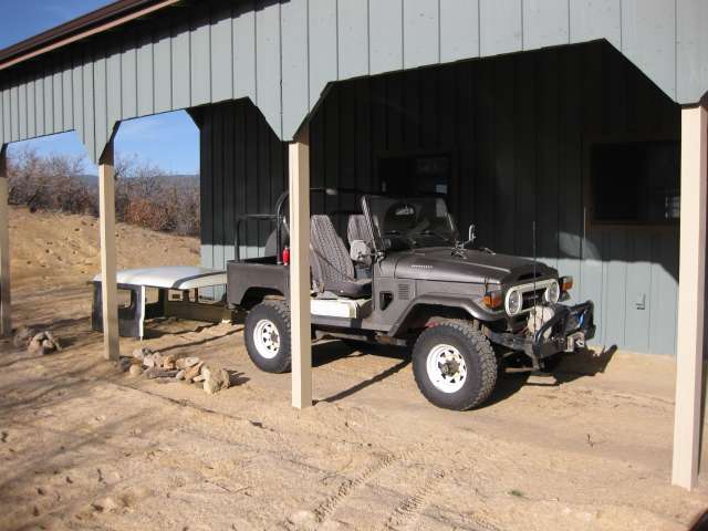
Removing the top for the summer - ready to go under the knife!
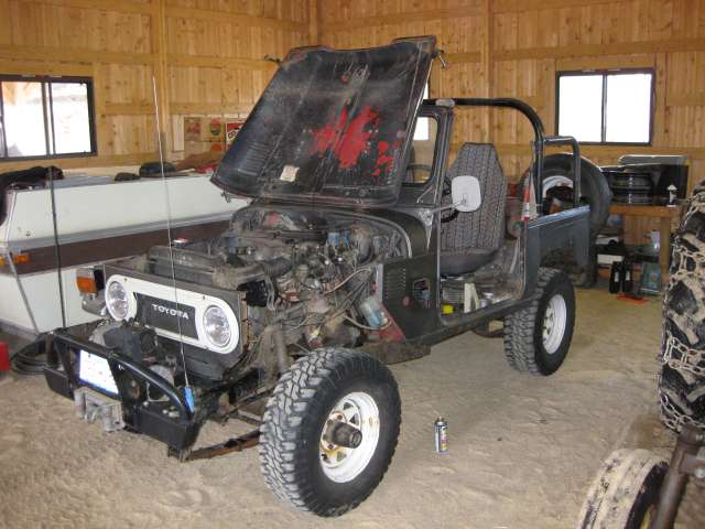
Getting some of the stuff out of the way
Shock Tower's gone!
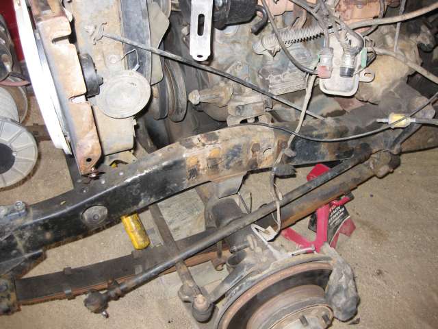
Steering column swapped out!
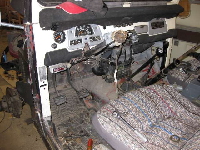
Steering box is gone!
FJ60 box is clamped to keep me psyched and give me an idea of some dimensions
On-Board Air pump looking for a new home!
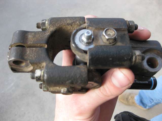
Giving an idea of what the intermediate shaft is going to look like
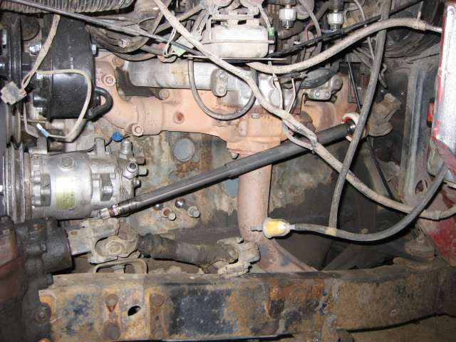
My next trip home I will have to disassemble/recombine some of the steering shafts I have so that I can have a good u-joint connection at the firewall and the steering box. The FJ60 steering shaft is collapsible, so that sleeve will act like a slip joint and allow the body and the frame to flex separately without binding the steering up.
Right now my plan is to mount the steering box flat on the frame (this is key to getting the J7 drag link to work because of the distances involved), sleeve the frame, and bolt through the frame when I mount the box. If the intermediate shaft pushes the steering box too much further forward, it will interfere with the radiator support and I will have to space the box out toward the tire about 1/4" or so to clear the radiator support. After some of my measurements today, this might have to happen anyway for the J7 drag link to work, so maybe it will all work out ok. I will find out soon whether the box will interfere with the radiator support.
After that there's not much I can do until I get my drag link parts. That will determine if/how much I need to space the box off the frame (if it isn't already needed because of the radiator support), and then I can start laying out my bolt hole pattern on the frame and make sure to locate the box so the pitman arm clears the frame but doesn't interfere with the springs when they are flexed either. I will also be able to finalize my shock tower location/orientation (whether they will be straight or bent, or spaced out from the frame as well).
Punch List:
1. I need to get the FJ55 column keyswitch removed by a locksmith (I don't have a key so I can't do it the kosher way and I don't want to destroy it) so I can use my current keyswitch.
2. I have to get some pipe for sleeving my frame and sharpen a bunch of drill bits so they are ready for use.
3. I have to get some plates (at least one, maybe two 1/4" plate) cut and drilled to the bolt pattern of my steering box.
4. I have to get a plate made in place of the EGR pipe that connects to the exhaust manifold.
5. Once I figure out the shock tower locations, do some measuring (might have to wait until steering is done I guess) and figure out what shocks I need to get (thinking Bilstein).
6. Figure out what I'm going to do about a return line cooler (I decided I'm going to buy a tubing bender for $15 and try to rebend the tubing to fit where I want it to go, in front of the radiator behind the grille).
7. There's a plate on my frame, welded in front of my steering stabilizer. It isn't really doing all that much good (maybe a little bit), but it's mostly in the way, so I'm going to have to cut that off too.
The goal is that on May 15th I will be ready to take it to a welder and have him do the welding and fabbing that needs to be done to make this happen.
So here's the breakdown:
-FJ40 steering wheel
-FJ60 steering box
-LHD J7 drag link end
-LHD J7 drag link tube
-v2.0 - stock FJ40 tie rod end with drag link connection reamed out to fit abovementioned J6 drag link end (reaming done by Cruiser Outfitters)
-FJ40 tie rods (small taper)
-FJ40 knuckles (small pattern)
-Ford F-250 shock towers (not straightened)
-GM Saginaw power steering pump
-JT Outfitters bracket,
-FJ60 power steering cooler, rebent to mount in my FJ40.
On v1.0 I had 40/55/60/70/GM steering, for v2.0 I have 40/Datsun/Borgeson/60/70/GM steering
I liked the FJ60 box because I saw it could work, for some reason I never really liked the idea of full Saginaw conversions, and I didn't want minitruck because it keeps all of the relay rods etc. which I consider to be "unnecessary" and just add more places where slop can develop. Currently my steering has quite the wander, mostly because of my steering box (I put on new TREs and rebuilt the Center Arm before I finally saw the steering box itself had slop) and this is my solution.
Here's some questions I asked on IH8MUD about the differences between Saginaw boxes and FJ60 boxes
I wanted to use an FJ60 power steering pump, but the Saginaw has more boost I understand and since my block wasn't tapped for the stock power steering pump bracket, I figured I would go with the JT Outfitters bracket because I could fit either the stock air pump or a Sanden air pump underneath the power steering pump and have factory emissions or OBA.
The beauty, I think, of what I'm going to try and do here, is that I'm going to use a modified Land Cruiser drag link. No custom drag link (though if I were running heavier duty TREs etc. I would go that way for sure), and no sleeving/cutting and welding a drag link together (I definitely don't want this to fail on or off road). After doing some measuring and figuring I *should* be able to use a LHD J7 rebuildable drag link end at the pitman arm, a J7 drag link tube, and the driver's side TRE from an FJ40. That way the threads, size, and taper should mate the J7 drag link tube to the FJ40 tie rod. More details to follow on that.
I'm also doing F-250 shock towers to allow a longer travel shock absorber, since I need new shocks anyway
Previous Work (besides all the figuring, talking, sketching, and daydreaming about FJ60 power steering
Tools needed
1. Pulley installer/remover kit ($12 at Harbor Freight)
2. Various box end wrenches/ratchet/sockets
3. Vice
4. Torque wrench (up to 90 ft-lbs for the head bolts)
(two sets of hands helps, but not necessary)
(Note: If you're using the JTO pulley (which I would not recommend, there's a better solution), it goes on with the grooved part of the hub facing out; the clamshell of the puller has to be able to attach to it if you ever want to get it off, plus that's the only way it will align properly and not interfere with the fan)
The JTO-style pulley needs to be installed something like this (stolen from Treeroot):
I bought a Saginaw pump and pulley from JT Outfitters along with the bracket to mount it to the front two exposed head bolts. I figured I could at least get that figured out and mounted to the truck, to make sure there were no surprises there. Well lo and behold there were some surprises. I put the pulley on backwards and thus could not get it off with the puller (there is a place on the hub for a clamshell to catch and pull the pulley off, but if it's on backwards it won't work). So I had to order a new pulley, cut a pie-shaped wedge out of the old one, then chisel it until it slid off. Then install the new pulley and mount it to the head bolts. Mounting it to the truck was pretty easy, once the pulley was on correctly
EDIT: should have just gone with the Volvo pulley in the first place, would have been a lot easier and less $$ shelled out in the long run.I also spent 4 hours last week cutting/straightening and welding the Ford shock towers (and bs-ing with Ige). I did this because I wanted to keep from cutting the fenders. But they have to be cut anyway for the steering box, and mine are rusty anyway, so I don't know why I'm making a big deal about it. I think there's going to be interference with the steering box as well, so I was probably jumping the gun a bit to do that, but I can always reverse those kinds of things right?
EDIT: should have not straightened the shock towers, shoulda just left them as-isDay 1 (or "It's amazing what you can do with an angle grinder and a couple of hours of your time): April 26, 2009 - 8 hours
Tools needed
1. Angle Grinder with cutoff wheel and grinding wheel
2. Various box end wrenches (loving my stubby Gear Wrenches)/ratchet/sockets
3. Various screwdrivers
4. C-clip pliers
5. Small Sledge/mallet
6. TRE puller (finally bought one - NOT a pickle fork but a puller - $25 at NAPA)
7. C clamps to clamp p/s box to frame for mockup
8. Tape measure
(Note: PB Blaster helps in the rusty bolt arena of getting stuff off - I broke two today)
1. I removed the doors and hard top just 'cause.
2. I removed the shocks. I don't know how old they are, they could be OEM, at any rate they don't work all that great. Since it's just past 4 years I've owned this truck I figure I'd better replace them
3. I removed the Center Arm and detached it from the steering stabilizer, drag link and relay rod. If anybody needs a good Center Arm let me know, I rebuilt it a couple years ago and it's in pretty good shape. I actually think I have a couple of these now.
4. I removed the apron and fender to give myself some workspace and put my truck up on blocks so I could take the tire off.
5. I removed the driver side shock tower. At first I tried to be nice, I thought I could buzz the rivets down then punch them into the frame and pull off the shock tower. Not so today, those rivets are VERY TIGHT in the frame. So I switched to the cutoff wheel and cut the corners off then beat it off with a small sledge. That was fun
(at this point I'm committed to a new shock tower arrangement)6. I removed the steering column and rag joint. It took me a while to figure out that there was a c-clip holding the lock cylinder on the shaft, once I found it it was only a couple minutes to slide that off and slide the inner steering column through the firewall.
7. I removed the steering box. First I scraped off the gunk and unbolted the box from the pedestal then I cut the pedestal (see I can learn too!
) then beat it off too. (At this point I'm committed to new steering)8. Once I had the frame cleared, I mocked up the FJ60 steering box with a couple clamps to get it in the approximate position. I then took some measurements to the tie rod to see if my J7 solution to the drag link will work. I think it will, so I will order the couple parts I lack on that end and get that mocked up in a couple weeks.
9. I mocked up the Sanden OBA pump that Neil Quigley let me borrow. I'm going to have to convince him to sell it to me
I think it will be a good use of space and will give me the functionality I want. I can run it off the p/s pump belt, and there should be sufficient wrap for both to work well.10. I mocked up the intermediate shafts, just trying to see what's going to have to happen. I need to recombine some u-joints and then I should be able to set where the steering box will sit on the frame. I'm hoping there will be enough room to fit the F-250 shock tower behind it without interfering with the fender support. If I get really lucky I won't have to relocate the shock tab on the axle.
11. Started making a list of all the things I'm going to have to figure out before I'm through with all this
Removing the top for the summer - ready to go under the knife!
Getting some of the stuff out of the way
Shock Tower's gone!
Steering column swapped out!
Steering box is gone!
FJ60 box is clamped to keep me psyched and give me an idea of some dimensions
On-Board Air pump looking for a new home!
Giving an idea of what the intermediate shaft is going to look like
My next trip home I will have to disassemble/recombine some of the steering shafts I have so that I can have a good u-joint connection at the firewall and the steering box. The FJ60 steering shaft is collapsible, so that sleeve will act like a slip joint and allow the body and the frame to flex separately without binding the steering up.
Right now my plan is to mount the steering box flat on the frame (this is key to getting the J7 drag link to work because of the distances involved), sleeve the frame, and bolt through the frame when I mount the box. If the intermediate shaft pushes the steering box too much further forward, it will interfere with the radiator support and I will have to space the box out toward the tire about 1/4" or so to clear the radiator support. After some of my measurements today, this might have to happen anyway for the J7 drag link to work, so maybe it will all work out ok. I will find out soon whether the box will interfere with the radiator support.
After that there's not much I can do until I get my drag link parts. That will determine if/how much I need to space the box off the frame (if it isn't already needed because of the radiator support), and then I can start laying out my bolt hole pattern on the frame and make sure to locate the box so the pitman arm clears the frame but doesn't interfere with the springs when they are flexed either. I will also be able to finalize my shock tower location/orientation (whether they will be straight or bent, or spaced out from the frame as well).
Punch List:
1. I need to get the FJ55 column keyswitch removed by a locksmith (I don't have a key so I can't do it the kosher way and I don't want to destroy it) so I can use my current keyswitch.
2. I have to get some pipe for sleeving my frame and sharpen a bunch of drill bits so they are ready for use.
3. I have to get some plates (at least one, maybe two 1/4" plate) cut and drilled to the bolt pattern of my steering box.
4. I have to get a plate made in place of the EGR pipe that connects to the exhaust manifold.
5. Once I figure out the shock tower locations, do some measuring (might have to wait until steering is done I guess) and figure out what shocks I need to get (thinking Bilstein).
6. Figure out what I'm going to do about a return line cooler (I decided I'm going to buy a tubing bender for $15 and try to rebend the tubing to fit where I want it to go, in front of the radiator behind the grille).
7. There's a plate on my frame, welded in front of my steering stabilizer. It isn't really doing all that much good (maybe a little bit), but it's mostly in the way, so I'm going to have to cut that off too.
The goal is that on May 15th I will be ready to take it to a welder and have him do the welding and fabbing that needs to be done to make this happen.
Last edited:

 . It's cheaper to order the rebuild kit with all 4 ends than it is to order just this one...going to wait and see if they come up with any solutions...Specter's kit is $179. EDIT AGAIN: Don was able to find a 70 series drag link end for a "reasonable" price and it should be here this week.
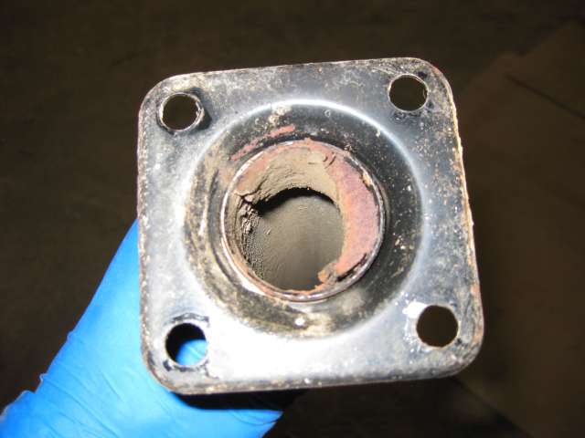
 )
)