
DaveInDenver
Rising Sun Ham Guru
Watched this video where the fella tested crimping, soldering and crimped & soldered Anderson connectors. His results (which may conflict or reinforce your bias, if you have one) are worth discussing since he talks theory and methods. His test is basically sound, no reason to dispute that he got the outcome he did.
Anderson crimp vs solder
View: https://www.youtube.com/watch?v=TSzUA0T1YD4
The topic is important as a general subject since there's more to it than just finding the lowest resistance.
For one technique and workmanship are critical. If I had one question it would be that his crimps might not be ideal. Anderson, like all manufacturers, has a procedure to produce a correct crimp which requires the right tooling and validation that the tools are working right.
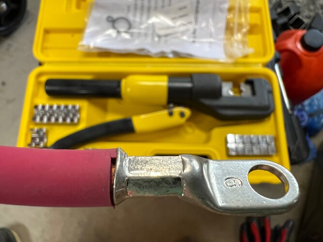
One complaint I make often is cheap hydraulic crimping tools are usually bad news. Their dies are not sized correctly and they can put too much force into the crimp, causing an over crimp. My suspicion is this is the root of why he found what he found. Your crimp needs to reach the cold weld point, where the terminal and individual wire strands all gets pushed together so there's no space and start to become one homogeneous mass, and no further. If you keep squeezing beyond this point the cross section of the wire/terminal starts to neck down. Copper being malleable will displace or in the worst case shear strands. So you'll go from correct gauge to fatter just ahead of the crimp where the material got pushed to thinner in the neck. It's this thinner section where your resistance will spike.
Also, the application on cars dictates that you balance absolute ideal electrical performance with mechanical reliability and environmental compatibility. Having a slightly higher finished resistance is preferred if the termination is more reliable. Soldering introduces several unknowns, which is why you usually only see crimped connections in car wiring harnesses. And aircraft and spacecraft.
So another video showing some of this. He also touches on test methodology and why doing low current testing on a heavy conductor such as this puts into question your results. In the first video he talks about test equipment resolution and error and the second video talks about this as it relates to small vs large magnitude in a large conductor. You may very well see a difference at low voltage/current that at actual high voltage/current are insignificant. IOW, having a connection that dissipates 5W is 50% loss in a 10W circuit but at 1000W is 0.5% loss. The numbers in such a case just tell you information, whether it's a problem (heating, voltage drop, etc) or not is up to you.
Solder vs crimp
View: https://www.youtube.com/watch?v=rJR7hpBOI0o
Anderson crimp vs solder
View: https://www.youtube.com/watch?v=TSzUA0T1YD4
The topic is important as a general subject since there's more to it than just finding the lowest resistance.
For one technique and workmanship are critical. If I had one question it would be that his crimps might not be ideal. Anderson, like all manufacturers, has a procedure to produce a correct crimp which requires the right tooling and validation that the tools are working right.
One complaint I make often is cheap hydraulic crimping tools are usually bad news. Their dies are not sized correctly and they can put too much force into the crimp, causing an over crimp. My suspicion is this is the root of why he found what he found. Your crimp needs to reach the cold weld point, where the terminal and individual wire strands all gets pushed together so there's no space and start to become one homogeneous mass, and no further. If you keep squeezing beyond this point the cross section of the wire/terminal starts to neck down. Copper being malleable will displace or in the worst case shear strands. So you'll go from correct gauge to fatter just ahead of the crimp where the material got pushed to thinner in the neck. It's this thinner section where your resistance will spike.
Also, the application on cars dictates that you balance absolute ideal electrical performance with mechanical reliability and environmental compatibility. Having a slightly higher finished resistance is preferred if the termination is more reliable. Soldering introduces several unknowns, which is why you usually only see crimped connections in car wiring harnesses. And aircraft and spacecraft.
So another video showing some of this. He also touches on test methodology and why doing low current testing on a heavy conductor such as this puts into question your results. In the first video he talks about test equipment resolution and error and the second video talks about this as it relates to small vs large magnitude in a large conductor. You may very well see a difference at low voltage/current that at actual high voltage/current are insignificant. IOW, having a connection that dissipates 5W is 50% loss in a 10W circuit but at 1000W is 0.5% loss. The numbers in such a case just tell you information, whether it's a problem (heating, voltage drop, etc) or not is up to you.
Solder vs crimp
View: https://www.youtube.com/watch?v=rJR7hpBOI0o
Last edited: