Building a ground plane, 2M/70CM

Corbet

Moderator
Staff member
Joined
Oct 24, 2006
Messages
10,190
Location
Durango, Colorado
I’m thinking about moving my HAM antenna off my front ARB bumper and to the rear of the vehicle to make room for a GMRS up front. I don’t want them both up there. The passenger side is not too distracting but I don’t think I could handle one right in front of me.

What’s the thought of cutting a 12” round or square piece of 1/8” steel and mounting that above the spare tire to act as a ground plane and then centering the antenna on that surface. Do you think I’ll gain or hurt the performance of the antenna? Reading about home built ground plane antennas it seems most have the outriggers the same length as the antenna itself. This will not be the case here.

A roof top mount is not possible. I’ve had the fender style mounts up by the cowl of the hood but I simply broke too many antennas on vegetation. I did the upper hatch mount at one point but that is not ideal with the RTT and awning.

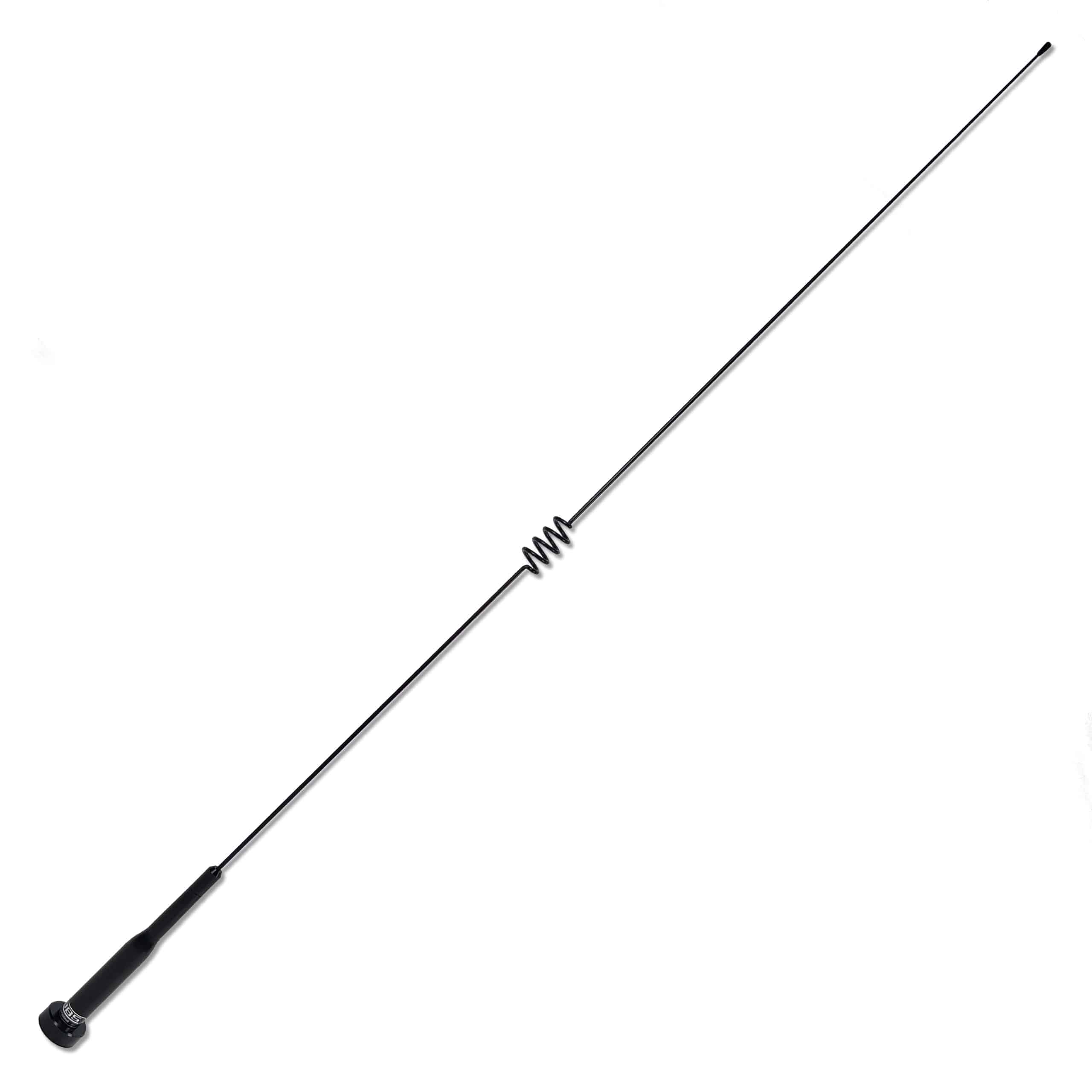
Current antenna is a Comet 1/2-wave (2M). Seems like every time I remove an antenna the base fails and breaks due to corrosion. So I could be forced to buy a new antenna, could change to a different size/model/style. Wouldn’t really want to go any longer unless foldable.


Or is this a waste of time and just mount it anywhere on the tire swing arm all Willy Nilly and just go wheeling. After all my antenna is ground independent.

See red line in picture. Tire is a 12.5” so I don’t want to go any wider than that for the steel base.

IMG_1370.jpeg
 
Last edited:

rover67

Rising Sun Member
Joined
Nov 1, 2007
Messages
9,745
Location
Boulder, Co
What are you after? functional antenna or are you chasing ideal receive/transmit with a tuned antenna? If the former (and I don't see why not) just toss what you have back there and be done. Another option would be a regular 2m 1/2 wave whip with the coil at the base.... they are pretty resilient to damage but won't do 70cm.. One of those back there (with the whole truck in front of it) would happily flail about in brush and if it breaks it's a simple whip replacement. Otherwise maybe build a ground plane for a different antenna like you are thinking..

The nitinol Sti-Co antenna will do 2m/70cm when tuned and is indestructible but needs a ground plane. I feel like adding a ground plane would make anything more susceptible to damage since it'll be an extra part that needs to be somewhat rigid. Maybe a simple sheet metal disk would work and fit neatly above that tire tho, I bet you could also work somethin up that has this kind of design, make a basic mount and strap it to the tire with a ratchet strap though I'm not sure how the whole truck in front and above it would affect it.. probably need some tuning when mounted and will radiate weird:

1774456628018.png
 

Corbet

Moderator
Staff member
Joined
Oct 24, 2006
Messages
10,190
Location
Durango, Colorado
I’m planning to rebuild both swing arms this summer so I’m taking the opportunity to not leave any antenna performance on the table. But I don’t need to geek out that much. Just want reliable coms.

I looked at a bunch of antenna builds online like you posted above. Not really the direction I want to go. My current antenna seems to work great. Just wondering if building a metal disc below it is worth the effort.
 

DaveInDenver

Rising Sun Ham Guru
Joined
Jun 8, 2006
Messages
14,252
Location
Grand Junction
There's several concepts at work here.

Understand that an antenna has a radiating element and the return. RF is a circuit just like electrons flowing in an light or winch circuit. You have a voltage source that will push current that travels along a wire to a load and that current needs a path to return to the source. The load in the case of RF is the excitation of the electrons floating in the air and space around you rather than a filament or motor windings.

If you remember your basics class the most simple antenna is a 1/2 wavelength dipole where each leg is 1/4 wavelength. This antenna is completely contained and works without any outside help.

You can electrically trick the RF to use only the radiating half if you connect the return half to a conductive ground. This is the standard 1/4 wave monopole.

simpleantennas.png

This antenna is mostly self contained, you don't need anything special for it to work as long as the fake half is electrically suitable.

So if you look at @rover67's instructions you'll see they tell you a radial length to cut, which is just slightly shorter than the main element. The reason it's slightly shorter we'll just leave to RF black magic but just recognize that this fake counterpoise/return half needs to be about 1/4 wavelength like the half of the dipole.

So a 12" disk isn't going to work well, it needs to be ~19". For UHF (70cm and GMRS) this is smaller, about 6".

Now that said a compromised counterpoise will still work, just less efficiently and produce a less predictable impedance and radiation pattern.

If you give a 1/4 wavelength monopole no counterpoise at all it will still try to find its return, which could be the truck body or the shielding braid of the coax. The problem is if this happens the radiated pattern could be terrible and the impedance may be wildly off. Using the coax braid for the counterpoise is also a recipe for creating RF interference with anything near by, like your cell phones or car stereo. It means you're also not radiating much of your RF outside the truck.

Which brings us to the next step. Let's just assume you can't do a suitable counterpoise but still want an antenna. You can change the monopole length to 1/2 wavelength. The funny black magic thing is it doesn't need the counterpoise like a 1/4 wavelength monopole.

We call these ground plane indifferent antennas. I'll use the marketing term no ground plane but understand that's not completely correct. Adding a ground plane will help with stabilizing impedance and making antenna's pattern uniform. It just does not need a ground plane strictly speaking to do the work of exciting electrons in space.

There are variations of these themes. Multiple elements to trick the antenna into working (like you'll see the term "stacked elements"), various inbetween lengths like 5/8 that are a little bit of both 1/2 and 1/4 charateristics. Some antennas will use a dipole inside the housing and run a short connection from the base to the middle, which is known as an elevated feedpoint.

In all cases an atenna need the electrical path (basically a DC one you can measure with a simple multimeter) back. This is not negotiable, the mount needs to be well grounded and the whip insulated from shorting to ground. This is true with all mobile antennas, not just NGP types.

You want a countinuous low impedance RF path from the mount to the radio. On a roof this is easy because the body does that. What a lip, bumper or swing-out you have to make sure it happens, which is typically done with a solid mount through the bolts to the frame or alternatively braid back to the common reference, the truck's body where the radio is also grounded.

braid.jpg

The real gotcha of a NGP is it changes the feedpoint from a 50 ohm compatible to a very high impedance (about 5000 ohms). So you can't just hook it up to a 50 ohm coax and 50 ohm radio. A NGP antenna will need a special circuit at it's feedpoint to do the translation. We call this an impedance matching network.

I mention this mainly so that no one thinks they can just cut a whip to 1/2 wavelength and use it. When you use a NGP antenna the whip will have to stay with it's original base to work, which is where the matching network lives.

tl;dr

The easiest way if you use a 1/4 wavelength is a 19" disk or radials.

The compromise is a small disk and tune to best SWR and live with the weird pattern. You might not achieve a very low SWR but as long as you get below 3:1 you shouldn't have much risk of damage and will work fine for convoy-scale comms. A 3:1 SWR is 75% efficient (meaning 25% is reflected and lost). At 2:1 you're getting about 90% efficiency. I call a tune good 'nuf at 1.5:1, which is 96% efficiency.

The next option is "no ground" type. Probably will not need a plane but check manufacturer's recommendations.

In all cases you need to provide a good electrical ground path.

The "good" path means you scrape paint to get bare metal and use braid to jump breaks like swing arm hinges, body panel gaps, body mounts, etc. If you don't provide this path the RF may try to use the coax shielding braid, which you don't want.
 
Last edited:

DaveInDenver

Rising Sun Ham Guru
Joined
Jun 8, 2006
Messages
14,252
Location
Grand Junction
Just wondering if building a metal disc below it is worth the effort.
As I puked above using a 1/4 wavelength the disk is required. If you do use 1/4 you need a full sized disk ideally.

If you're using an antenna that doesn't need a ground plane then a small disk is optional but isn't going to hurt and may have some benefit to keeping the pattern from drooping towards the road where it does no good.

On that last point, about not letting RF just heat the Earth, I neglected to mention that what is important with a mobile antenna is height. Marco touched on it. An antenna mounted on a fender lip will have great function across the hood and reduced performance to the opposite side. The cab will block behind you.

Think of RF like a light, your antenna the bulb source of that light and then imagine RF being sort of blocked by things.

But if you elevate the whip then that rearward performance is improved.

It's the same with a rear door lip mount or one you put on a bumper or tire carrier. If you can move the whips above the roof and RTT the performance is going to be better towards the front.

If it was me I'd find an antenna that does not need a ground plane (which your SBB-2 SBB-5 is fine, it does NOT need a plane under it) and focus on getting the antenna high and the mount a good continuous path back home. A small disk wouldn't hurt but I doubt you'd really notice much difference with an SBB-2 or similar.
 
Last edited:

RDub

Hard Core 4+
Joined
Feb 9, 2021
Messages
509
Location
Boulder, CO
@DaveInDenver how does electrically grounding the antenna apply when using an external antenna “coaxed” to a handheld radio? For example, using a cheap GMRS HT and external whip as a low cost convoy comms unit. Is it best to ground the HT to the antenna ground (car body/chassis) at the outer braid side of the antenna connector on the HT? Sorry to hijack.
 

Corbet

Moderator
Staff member
Joined
Oct 24, 2006
Messages
10,190
Location
Durango, Colorado
@DaveInDenver

Based on your last post, mounting a folding version of my antenna on the roof rack could be the best solution. I will admit I feel like my best radio performance was with my rear upper hatch mount antenna I originally had. It was a folder so I could drop it when needed. If I go above my spare that will be almost as high with the advantage of swinging clear of my 270° awning. Roof rack real estate is non-existent now with my hard shell tent.
 

DaveInDenver

Rising Sun Ham Guru
Joined
Jun 8, 2006
Messages
14,252
Location
Grand Junction
@DaveInDenver how does electrically grounding the antenna apply when using an external antenna “coaxed” to a handheld radio? For example, using a cheap GMRS HT and external whip as a low cost convoy comms unit. Is it best to ground the HT to the antenna ground (car body/chassis) at the outer braid side of the antenna connector on the HT? Sorry to hijack.
Ground in this case is another name for a common reference point. I am being pretty loose with the term.

An important recognition is that anything conductive (steel, aluminum, copper, etc) in the region *may* couple RF and become an element in the antenna. But just because it *may* doesn't mean it *will* become part of the antenna.

In a perfect world the radio produces it's RF, there's a ideal match to the coax, which acts like a ideal transmission line and all that RF goes into an ideal antenna feedpoint and is radiated out in space on an ideal radiator that's balanced by an ideal counterpoise.

Nothing is perfect and there are hiccups along the path. We call these discontinuities impedance mismatches. Each one causes a reflection, which is literal, a small amount of incident RF is reflected back (this is where a standing wave is created, e.g. SWR is standing wave ratio).

As long as you have everything you need for a good antenna nothing is reflected. It's when you don't that RF finds it's own uncontrolled path back home to the radio, which you want to avoid. Worst case is the coax shield being the fallback easiest path. This is by the way not always bad that the shield radiates. It just is in most cases and is for us because the RF is now inside the truck between the radio and whip. It's doing no good work and creating a bunch of interference inside.

The reason we have to be more careful with mobile radios is the coax outer ring and physical case of the radio are mounted to the body and powered from the battery, which is also connected to the body and frame. This complicates what might be antenna metal in the truck so practically you need to make everything that might act as counterpoise between the radiating element and the radio be invisible, which is achieved by being at the same RF and electrical potential. Any gap or break in the path creates a new impedance and that makes a new antenna or short circuit for the RF.

HTs avoid this by being powered from their own battery or having isolation in the power adapter. Then the only potential alternative path is the coax itself, which won't come into play if you've given the RF a good antenna system so it can do it's work.

If you tie the shield to the car at the radio then you have to be aware of everything in between just like with a mobile radio. It's better to leave it isolated and provide a counterpoise around the antenna (if it even needs one, a NGP might be balanced by design). The antenna mount can be grounded to the car body but as long as the radio is isolated that won't matter. It only impacts the counterpoise immediately around the whip.

tl;dr: What this means practically speaking is leave the HT isolated and put the mag mount on a decent area of sheet metal or if in doubt (like a fiberglass roof) on a suitably sized disk. The antenna is complete and you're done.

Additional thoughts:
In normal use an HT is uses it's own case or anything touching it (like YOU) as the counterpoise. This is an important reason HTs are low powered. The designer also anticipates this so the radio is designed such that RF on the case can't upset the circuits inside. A good mobile does this as well but you don't expect the case to be part of the antenna at full power so you balance cost of labor and parts.

Some people looking for better performance from their HT or portable radios will give the radio an explicit counterpoise in the form of a wire from the radio or remotely mounted antenna. If you look into portable HF operators (they're called manpack radios) you'll see this a lot and the wire is sometimes known as a tiger, cat or rat tail.

There is a possibility where a floating but still conductive element can react. This is where the discussion of near and far field elements and yagi elements comes into play. It's not really important here because you'd have to have lengths of metal that are perfectly long and spaced on critical wavelengths for that to occur and the antenna impedance to be affected (which is how the radio will care). Not impossible just unlikely. I only mention it if someone wants to research it more. Most of the time metal that isn't part of the antenna system will just absorb and reflect RF in a way that can distort the pattern but it won't directly upset your radio.

fieldzones.png

yagi.gif
 
Last edited:

CardinalFJ60

Rising Sun Member
Joined
Aug 23, 2005
Messages
2,890
Location
Lafayette
I love this stuff!!! Thanks everyone.
follow up question regarding coax length and resistance.

When tuning @nakman ’s antenna, my mfj 269 showed about 10ohms instead of close to 50. We shortened the coax to the length of run. Don’t know the length.

Whats going on there? Any positive or negative effects?
 

Inukshuk

Rising Sun Member
Joined
Aug 24, 2005
Messages
8,609
Location
Denver, CO
@DaveInDenver :cool:

1) What is the BEST NMO NGP 2M and GMRS in a folding style and does folding style degrade performance?
2) What is the BEST NMO NGP 2M and GMRS in a non-folding style?
3) Is a GP antenna inherently better than NGP?
4) Would a metal plate 6" wide and 46" long, where the antenna is centered on the 6" axis and offset about 10" on the 46" axis be a good GP?

@CardinalFJ60 need to meet and tune!
 

DaveInDenver

Rising Sun Ham Guru
Joined
Jun 8, 2006
Messages
14,252
Location
Grand Junction
I love this stuff!!! Thanks everyone.
follow up question regarding coax length and resistance.

When tuning @nakman ’s antenna, my mfj 269 showed about 10ohms instead of close to 50. We shortened the coax to the length of run. Don’t know the length.

Whats going on there? Any positive or negative effects?
Where did you read 10Ω?

Let's talk SWR, antenna analyzers and the MFJ-269 specifically.

The first thing to know is we are measuring an impedance, not a resistance. The difference is an impedance is the measure of DC resistance and AC reactance. Reactance is the combination of all the capacitance and inductance in the circuit.

You will never actually read a perfect 50Ω. Even measuring a dummy load you'll only see something close.

I put a 50Ω dummy load onmine. This is a Motorola dummy load usable for DC up to about 1 GHz at 100W. It measures 48.9Ω with a multimeter on DC resistance. The actual construction is a big fat wirewound resistor with fins for cooling and a connector on the end.

With a short RG-58 jumper I get roughly 52Ω but that is actually 51+j5Ω at 144.34 MHz and this represents an SWR of 1.1:1 (come back to this).

The meter is seeing 51Ω of DC resistance and j5Ω of AC reactance. This is sometimes call the real and imaginary part or a complex impedance. The real part is real because it's resistance. It's the part that makes heat and moves motors and creates light. The imaginary part is because you have to imagine it exists. It's complex because it's the energy in the electromagnetic fields of the capacitors and inductors in the circuit. It doesn't do real work but it requires energy.

The power company worries endlessly about this because they only get paid based on the real part but they have to still generate all the energy for the imaginary part. So they correct the power line impedance to be as close to zero so complex impedance is the same as real resistance.

The reasoning behind this is reactance can be either positive or negative, which ultimately represents the voltage or current phase of the real to complex. A capacitor's current leads the real current while inductance lags. So if you're using an inductive load, like your washing motor, you're causing the impedance to slightly lag. They will zero this back by using a capacitor that has the same impedance as the inductor.


IMG_5001_mid.png

Using a really long length of RG-174 with the same dummy load gives me 54+j4Ω of impedance. All that's changed is the length and type of coax. Still a calculated SWR of 1.1:1 on it. The difference is RG-174 being smaller has slightly different properties. It's still 50Ω characteristic impedance.

IMG_4999_mid.png

When I put the analyzer on a real antenna at the same frequency I get 43+j23Ω with an SWR of 1.6:1 now. But notice how the right meter always shows roughly 50Ω under the needle? This is fine, I have a ton of RG-8, a radiating element and a counterpoise in the circuit. All this has capacitance and inductance. The antenna itself is a Diamond X30 on my roof. It's a big version of your SBB-2 SBB-5, a 1/2λ on 2m and phased 5/8λ on UHF with a matching network in the base and small radials. One could figure all the components out and see if this makes sense but it's a lot easier to collapse the whole thing into one characteristic impedance.

IMG_4998_mid.png

The reason behind this is the single number by itself is an approximation of what's actually happening, what we call the "characteristic impedance" of what I'm showing.


There's a lot of theory and math behind all this. I mean, a whole lot. And it's important but also it's not really important. It depends.

You need to look at the impedance the 269 is giving you as well as the SWR.


You need the SWR to be low because that's what's ultimately showing you how well you've matched things up. Impedance is important because that tells you why the SWR is what it is.

An antenna has no real component, it's wire that goes nowhere. It's got an impedance that is 50Ω and it's all imaginary. The impedance at the feedpoint is created by the radiation resistance of the antenna being physically close but not touching it's counterpoise, the other half of the dipole. If it touches it shorts. If it's too wide then it doesn't couple. The porridge needs to be just right to make a 50Ω feedpoint impedance. Here again, more science and math. It's a physical gap with a dielectric between them at a particular frequency.

Then moving back the feedline, in our case it's coax. You could keep the conductors parallel with the same fixed gap and achieve the same thing. That's known as twin lead or window line. The reason we use coax is the EM field is fully contained inside while on twin lead the field surrounds the feedline, so for tight installations you experience less risk of interference.

There's a connection on each end of the feedline. This also has to keep the separation with a dielectric between them to avoid an impedance discontinuity.

Point is everywhere along the path there's resistance, capacitance and inductance that combined make your characteristic impedance.

And that connector is where I would first look for your issue. The PL259 is first not actually 50Ω across it's whole length even when done right. The SMA, N type, BNC do keep the impedance uniform across them.

Second the PL259 that you solder on are notorious for their difficulty doing right and the heat to get them to solder wrecks the foam dielectric in the coax, further screwing up the impedance.

With what I assume you measured (and please correct me) you saw 10Ω on the analog VU meter? That is not good. Was the SWR really high?

If it was 10Ω on one of the complex impedances values on the digital display but the analog still showed ~50Ω then it's probably OK. The SWR should be fairly low as long as the analog meter is close.

As far as cutting, the order isn't random. Your first assumption has to be you used the right coax or twin line. If you put a 75Ω coax then you will get a mismatch no matter what you do.

The next step is to figure out what's right and what's not. When you have a tuned antenna and good counterpoise the coax length is not important. The only time the coax length will affect SWR is when it's part of the antenna.

So if you trimmed the coax and that improved the SWR then your antenna system is not operating right.
 
Last edited:

DaveInDenver

Rising Sun Ham Guru
Joined
Jun 8, 2006
Messages
14,252
Location
Grand Junction
@DaveInDenver :cool:

1) What is the BEST NMO NGP 2M and GMRS in a folding style and does folding style degrade performance?
2) What is the BEST NMO NGP 2M and GMRS in a non-folding style?
Best is relative since it depends on what you want. Your question does not ask about gain and mechanical limitations. If you want uniform performance in all directions and minimal size a 1/4λ on 2m works great and happens to be 3/4λ on ham 70cm and pretty close still to resonance on GMRS. Both are essentially putting equal energy in a dome over and around you. If you cut the whip for 1/4λ on UHF then it will not be useful on 2m but will clean up the radiation pattern inherent with a 3/4λ (there's an odd null, see the chart below).

If you can tolerate a taller and heavier antenna I like the Larsen NMO 2/70B. It's NGP so doesn't need to be on a plane to work acceptably. The SBB-2 is similar, 1/2λ on VHF, stacked 5/8λ on UHF, with a matching network in the base and open center coil.

These antennas have gain, so they give up overhead performance for better horizontal. They are basically not working above about 50° but put about 2 dB more RF nearer to the horizon.

Trying to get more gain than this is not practical for general purpose. You just start creating more nulls. To do it effectively you need a directional antenna, e.g. yagi or dish or something.


antenna_patterns.png

The folding mechanism shouldn't make a significant difference if it's done right. The main problem RF-wise is it introduces a new spot for corrosion and that will cause issues.

3) Is a GP antenna inherently better than NGP?
Not really. The main advantage to a 1/4λ is that it doesn't need any matching network, which helps efficiency and reliability. But strictly on performance ground plane vs no-ground plane isn't an important factor.

That said like anything, when you add complexity you open a pandora's box for things to fail. If the caps and inductors in the matching drift or get water or broken from banging around the antenna stops working. Thus a budget is probably worth a mention.

If you want easy the performance a 1/4λ whip on the roof is stupid cheap and reliable for a minimal budget. There's nothing to fail and repair can be done with any reasonably stiff wire, welding rod or coat hanger.

If you want NGP then you need to consider quality. A Larsen like I have is $100 now but it's commercial grade and will probably bend the roof before it fails. And if it does fail Larsen has made the antenna for like 30 years and sells parts to fix it.
4) Would a metal plate 6" wide and 46" long, where the antenna is centered on the 6" axis and offset about 10" on the 46" axis be a good GP?
That would be fine on 70cm or GMRS. Off center will mean the radiated pattern may slightly favor the long side but not enough to worry about.

It would also work well electrically for a 2m counterpoise but would strongly favor long direction in pattern. It would make a 3D bow tie looking pattern.
 
Last edited:

Inukshuk

Rising Sun Member
Joined
Aug 24, 2005
Messages
8,609
Location
Denver, CO
Guess my diamond NR770hnmob is not a weak point (yes, the center contact and hinge are clean)
Thx!
 

DaveInDenver

Rising Sun Ham Guru
Joined
Jun 8, 2006
Messages
14,252
Location
Grand Junction
Guess my diamond NR770hnmob is not a weak point (yes, the center contact and hinge are clean)
Thx!
Is it giving you trouble? The configuration is the same as the Larsen I recommend and the SBB-5 @Corbet has, it's a proven dual band config that works.

You mention center contact, I have an ancient Comet C767 that I think has similar base. The one with the springy center pin? I found it wasn't a bad idea to take the antenna off and move that once in a while to break the corrosion. My Comet seems kinda weak sauce fragile, the coils are tiny (open coils like your Diamond are more rugged), the hinge sucks so I had to permanently afix it.

But it performs incredible. @Pskhaat may or may not remember a simplex QSO we had years ago, he was in Moab and I was on I-70 near Thomson Spgs, something like a 25 mile path with no elevation advantage. I had it on the ARB, not an ideal place at all.
 
Last edited:

Pskhaat

Locked
Joined
Apr 26, 2009
Messages
218
Location
38.0111,-109.9181
But it performs incredible. @Pskhaat may or may not remember a simplex QSO we had years ago, he was in Moab and I was on I-70 near Thomson Spgs, something like a 25 mile path with no elevation advantage. I had it on the ARB, not an ideal place at all.

Indeed that. I recall being behind the rocks'ish :-) At that time I had a quad-band comet on my 80s ARB.


Inukshuk

Rising Sun Member
Joined
Aug 24, 2005
Messages
8,609
Location
Denver, CO
Is it giving you trouble? The configuration is the same as the Larsen I recommend and the SBB-5 @Corbet has, it's a proven dual band config that works.
Other's seem to receive better than me.
You mention center contact, I have an ancient Comet C767 that I think has similar base. The one with the springy center pin? I found it wasn't a bad idea to take the antenna off and move that once in a while to break the corrosion.
I take it off to get in and out of my garage, so it gets worked and is clean.

I suppose I will see at CM how it performs on the new mount.

Thx!
 

DaveInDenver

Rising Sun Ham Guru
Joined
Jun 8, 2006
Messages
14,252
Location
Grand Junction
Other's seem to receive better than me
Talking GMRS or ham? Keep in mind reciprocity, an antenna performance RX is the inverse of TX. The antenna might be tuned for ham still?

The 2m and 70cm ham allocations have a relationship but if an antenna is tuned for ham GMRS is beyond optimal, which technically is known as the bandwidth if one wants to google.
 

Inukshuk

Rising Sun Member
Joined
Aug 24, 2005
Messages
8,609
Location
Denver, CO
Talking GMRS or ham? Keep in mind reciprocity, an antenna performance RX is the inverse of TX. The antenna might be tuned for ham still?

The 2m and 70cm ham allocations have a relationship but if an antenna is tuned for ham GMRS is beyond optimal, which technically is known as the bandwidth if one wants to google.
HAM. 146.460 and .580 usually
I run a Midland Ghost on a mag mount for the GMRS. I will try (a) GME antenna on same setup and (b) likely switching to using a GME unit in my green 80. The midland handset cable is falling apart and they do not offer replacements - my handset is the 8 wire MA275. Yes, likely I could find an 8 wire and a connector for inside the mic, but strain relief, etc. and the GME's in LongCruiser are easy enough to pop off the bracket and swap over.
 
Back
Top