CardinalFJ60
Rising Sun Member
I wish I took a photo. But it’s easy enough to retest on his rig.Where did you read 10Ω?
Let's talk SWR, antenna analyzers and the MFJ-269 specifically.
The first thing to know is we are measuring an impedance, not a resistance. The difference is an impedance is the measure of DC resistance and AC reactance. Reactance is the combination of all the capacitance and inductance in the circuit.
You will never actually read a perfect 50Ω. Even measuring a dummy load you'll only see something close.
I put a 50Ω dummy load onmine. This is a Motorola dummy load usable for DC up to about 1 GHz at 100W. It measures 48.9Ω with a multimeter on DC resistance. The actual construction is a big fat wirewound resistor with fins for cooling and a connector on the end.
With a short RG-58 jumper I get roughly 52Ω but that is actually 51+j5Ω at 144.34 MHz and this represents an SWR of 1.1:1 (come back to this).
The meter is seeing 51Ω of DC resistance and j5Ω of AC reactance. This is sometimes call the real and imaginary part or a complex impedance. The real part is real because it's resistance. It's the part that makes heat and moves motors and creates light. The imaginary part is because you have to imagine it exists. It's complex because it's the energy in the electromagnetic fields of the capacitors and inductors in the circuit. It doesn't do real work but it requires energy.
The power company worries endlessly about this because they only get paid based on the real part but they have to still generate all the energy for the imaginary part. So they correct the power line impedance to be as close to zero so complex impedance is the same as real resistance.
The reasoning behind this is reactance can be either positive or negative, which ultimately represents the voltage or current phase of the real to complex. A capacitor's current leads the real current while inductance lags. So if you're using an inductive load, like your washing motor, you're causing the impedance to slightly lag. They will zero this back by using a capacitor that has the same impedance as the inductor.
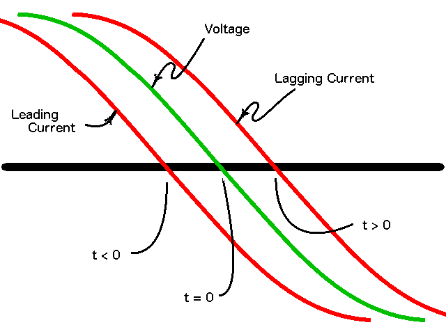
Leading and lagging current - Wikipedia
en.wikipedia.org
Using a really long length of RG-174 with the same dummy load gives me 54+j4Ω of impedance. All that's changed is the length and type of coax. Still a calculated SWR of 1.1:1 on it. The difference is RG-174 being smaller has slightly different properties. It's still 50Ω characteristic impedance.
When I put the analyzer on a real antenna at the same frequency I get 43+j23Ω with an SWR of 1.6:1 now. But notice how the right meter always shows roughly 50Ω under the needle? This is fine, I have a ton of RG-8, a radiating element and a counterpoise in the circuit. All this has capacitance and inductance. The antenna itself is a Diamond X30 on my roof. It's a big version of yourSBB-2SBB-5, a 1/2λ on 2m and phased 5/8λ on UHF with a matching network in the base and small radials. One could figure all the components out and see if this makes sense but it's a lot easier to collapse the whole thing into one characteristic impedance.
The reason behind this is the single number by itself is an approximation of what's actually happening, what we call the "characteristic impedance" of what I'm showing.

Characteristic impedance - Wikipedia
There's a lot of theory and math behind all this. I mean, a whole lot. And it's important but also it's not really important. It depends.
You need to look at the impedance the 269 is giving you as well as the SWR.

Standing wave ratio - Wikipedia
You need the SWR to be low because that's what's ultimately showing you how well you've matched things up. Impedance is important because that tells you why the SWR is what it is.
An antenna has no real component, it's wire that goes nowhere. It's got an impedance that is 50Ω and it's all imaginary. The impedance at the feedpoint is created by the radiation resistance of the antenna being physically close but not touching it's counterpoise, the other half of the dipole. If it touches it shorts. If it's too wide then it doesn't couple. The porridge needs to be just right to make a 50Ω feedpoint impedance. Here again, more science and math. It's a physical gap with a dielectric between them at a particular frequency.
Then moving back the feedline, in our case it's coax. You could keep the conductors parallel with the same fixed gap and achieve the same thing. That's known as twin lead or window line. The reason we use coax is the EM field is fully contained inside while on twin lead the field surrounds the feedline, so for tight installations you experience less risk of interference.
There's a connection on each end of the feedline. This also has to keep the separation with a dielectric between them to avoid an impedance discontinuity.
Point is everywhere along the path there's resistance, capacitance and inductance that combined make your characteristic impedance.
And that connector is where I would first look for your issue. The PL259 is first not actually 50Ω across it's whole length even when done right. The SMA, N type, BNC do keep the impedance uniform across them.
Second the PL259 that you solder on are notorious for their difficulty doing right and the heat to get them to solder wrecks the foam dielectric in the coax, further screwing up the impedance.
With what I assume you measured (and please correct me) you saw 10Ω on the analog VU meter? That is not good. Was the SWR really high?
If it was 10Ω on one of the complex impedances values on the digital display but the analog still showed ~50Ω then it's probably OK. The SWR should be fairly low as long as the analog meter is close.
As far as cutting, the order isn't random. Your first assumption has to be you used the right coax or twin line. If you put a 75Ω coax then you will get a mismatch no matter what you do.
The next step is to figure out what's right and what's not. When you have a tuned antenna and good counterpoise the coax length is not important. The only time the coax length will affect SWR is when it's part of the antenna.
So if you trimmed the coax and that improved the SWR then your antenna system is not operating right.


It showed 10ohms and swr was through the roof on the 269. (>31!)
We then hooked it up to a simple inline power/swr meter. Those swr readings were like 1.2.
@rover67 was doing it with me…Marco anything to add? I’m sure you recall my surprise when we were talking about those readings.