2UZ swap into 1992 FJ80

Stuckinthe80s

Rising Sun Member
Staff member
Joined
Dec 29, 2017
Messages
2,326
Location
Lakewood, CO
If you wanted an off the shelf item could you use something like this?:


But if you can use the donor speedo that seems cheaper.
Nice! I figured they would have something for this. They have been coming out with a lot of really cool tech the last few years to get over some of the engine swap hurdles.

@AimCOTaco is hooking me up with a speedo so I'm going to try that route and see how it goes. I'm also going to do some more reading to see if a Sequoia/4runner/Tundra/GX470/LS400 speedo would work as well. I would assume so, but who knows. As this is a thread intending to document all of this to help others get through this stuff, it will be good info to have.
 

Stuckinthe80s

Rising Sun Member
Staff member
Joined
Dec 29, 2017
Messages
2,326
Location
Lakewood, CO
You really should hang an oscilloscope at various places, that's the only way to know for sure.
I agree and I'm going to figure out how to get my hands on one.

My plan is to do a bench test something along the lines of:
1. Pull the speed sensor and hook it up to a drill or something to get it to produce a signal and find out what that signal is.
2. Connect the speed sensor to the speedometer (signal conditioner) to find out what the signal looks like afterwards.
3. Document everything and determine best approach to giving the ECU what it wants.
 

Stuckinthe80s

Rising Sun Member
Staff member
Joined
Dec 29, 2017
Messages
2,326
Location
Lakewood, CO
Well, I did some more digging in the speed signal, and without doing a bench test, I think I found out what output voltage should be. Looking in the FSM (not the EWD) it has some troubleshooting steps to follow on the back of the combination meter:
1644965455868.png


The B9 and B10 designators are associated with the plugs on the back of the meter:

1644965513299.png


The speedometer is a different configuration than what you showed from the 4runner @HDavis and I'm going to have to trace out the circuit on the associated "meter circuit plate":

1644965877480.png


The speedometer itself looks like just a display interface with the circuit board:

speedo 1.jpg


speedo 2.jpg
 

Stuckinthe80s

Rising Sun Member
Staff member
Joined
Dec 29, 2017
Messages
2,326
Location
Lakewood, CO
What is happening is the speed sensor is passive, just an AC waveform that more or less drives the speedometer, probably with just a linear amplifier to drive the motor (e.g. a voltage or current follower).

You could feed that AC sine wave into the ECU but the "error" they talk about is due to how a digital system sees signals. It wants to see voltages as either high or low. You can't hang out in the region between low and high without causing issues (called the switching or threshold region).

But if you impose a sine wave over a square wave you'll see that sine waves produce exactly the wrong type of signal for a system that wants to be either high or low. They actually spend almost no time as either zero or max and spend all the time slowly changing between them.

View attachment 102003

Without going into an even deeper tangent about digital design just realize that sine waves are terrible to feed into a digital input if you want to accurately represent it. Especially so when the signal you're reading is to measure frequency, e.g. counting the edges.

The basics here is if your signal is neither low (e.g. zero volts) or high (say 5V) and sits in between a digital input will randomly see it as low or high or might just oscillate between them until the right stable low or high is reached. The ECU might see a 15 Hz (just say it's on that order) speed sensor sine wave as going 500 MPH if it expects a 15 Hz square wave.

So you have to make the sine wave into a square wave. That's what the "conditioner" box is doing. It's making a slowly changing signal into one that changes very fast.

I'd probably shy away from modifying you gauge cluster unless you can figure out the circuit. It might still work fine or not. Potential problems is your speed stops working or begins to have errors or jumps around. It might also be unseen problems but is slowly ruining the speedometer motor. So I'd keep the VSS-to-gauge circuit as Toyota intended it personally.

I'd rather tap the VSS signal and use the conditioner. It wouldn't have to be on the gauge necessarily (like put a 'Y' in the harness at the VSS) and it wouldn't be difficult to hack something together if you can't find an OTS solution. At high level the circuit is very simple. The concept has been around since Moses was an EE undergrad.

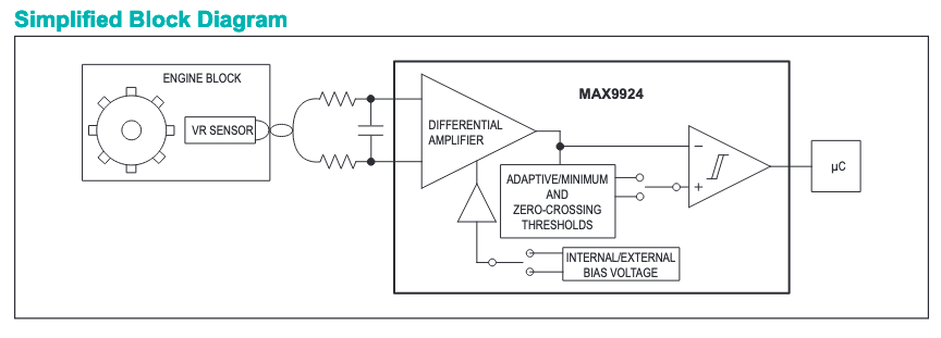
View attachment 102005
So just to do a sound check on what you are saying Dave, and combining it with the what the FSM says of the output needing to be between 1.5V - 5V, as long as the wave is within that voltage range, and is sharp (conditioned) the ECU should be happy, right? I'm making sure I'm not stuck so much on the value of the output but rather condition of the value.
 

Stuckinthe80s

Rising Sun Member
Staff member
Joined
Dec 29, 2017
Messages
2,326
Location
Lakewood, CO
I found this and went ahead and bought it:

1644984596648.png


It seems like it fits the bill and can be found here if anyone is interested:

https://sirhclabs.com/product/cortex-ebc-speed-sensor-adapter/

I figured it was worth it to be able to move onto something else instead of continuing to mess with this any longer. When everything is said and done, I'd still like to work through figuring the other stuff out, but we'll see.
 

DaveInDenver

Rising Sun Ham Guru
Joined
Jun 8, 2006
Messages
13,114
Location
Grand Junction
I found this and went ahead and bought it:

View attachment 102070

It seems like it fits the bill and can be found here if anyone is interested:

https://sirhclabs.com/product/cortex-ebc-speed-sensor-adapter/

I figured it was worth it to be able to move onto something else instead of continuing to mess with this any longer. When everything is said and done, I'd still like to work through figuring the other stuff out, but we'll see.
This box is pretty much what I had pictured in my diatribe.

Screen Shot 2022-02-16 at 7.14.11 AM.png
 

DaveInDenver

Rising Sun Ham Guru
Joined
Jun 8, 2006
Messages
13,114
Location
Grand Junction
So just to do a sound check on what you are saying Dave, and combining it with the what the FSM says of the output needing to be between 1.5V - 5V, as long as the wave is within that voltage range, and is sharp (conditioned) the ECU should be happy, right? I'm making sure I'm not stuck so much on the value of the output but rather condition of the value.
The troubleshooting description is a bit confusing. The use of a double arrow isn't helpful IMO. The FSM/EWD audience isn't an EE though.

I think what they want you to verify is that the sensor pulses swing sufficiently for the ECU to see high and low. The idealized description of digital logic (say TTL) is 5V = high or one and 0V = low or zero.

But in the real world there's a range of voltages that will recognized by the receiver circuit. In the case of standard TTL any voltage higher than 2.0V will be a high and any voltage lower than 0.8V is a low. The region in the middle is indeterminate. It could be low, high or oscillate between them. To account for this TTL drivers will guarantee their high output will be at least 2.4V (or higher) and their low will be no higher than 0.4V (or lower). This is what's called "logic levels" when talking about different families of logic (TTL, LVTTL, CMOS, LVCMOS, ECL, etc).

The significance of 1.5V could be that they're using a trigger and maybe a level shift in the ECU to square up edges. Also that it could be battery voltage makes me think the ECU designer has built in flexibility to feed it a 5V digital signal or 12V raw analog perhaps, so there may already be the circuit you need. I stress *may* in this case...

So I think what they're trying to check is that when the sensor swings over the tone ring the pulses produced transition over a wide enough voltage range is all.
 
Last edited:

FunkyYota

Rising Sun Member
Joined
Nov 6, 2019
Messages
305
Location
Evergreen
I found this and went ahead and bought it:

View attachment 102070

It seems like it fits the bill and can be found here if anyone is interested:

https://sirhclabs.com/product/cortex-ebc-speed-sensor-adapter/

I figured it was worth it to be able to move onto something else instead of continuing to mess with this any longer. When everything is said and done, I'd still like to work through figuring the other stuff out, but we'll see.
If this works for you I'll buy one too. :)

I've been thinking about playing with setting up cruise on mine as well. Just need to get some more time, and deal with the countless higher priority projects. I should just get a daily driver so I can leave my 80 in the garage for projecting on.
 

Stuckinthe80s

Rising Sun Member
Staff member
Joined
Dec 29, 2017
Messages
2,326
Location
Lakewood, CO
Nothing new right now but I did want to post this here to keep track of it:

1645121298438.png
 

mdimarzio

Brand New
Joined
Jun 17, 2022
Messages
1
I put this together the other day to get it straight in my head. I got my TAC working on my 91 2uz swap using Dakota Digital.
 

Attachments

  • 2uzswap-dakota-digital-tach.pdf
    351.9 KB · Views: 185

Stuckinthe80s

Rising Sun Member
Staff member
Joined
Dec 29, 2017
Messages
2,326
Location
Lakewood, CO
It’s been a long while and I really need to get motivated to get this thing finished so I thought I would post up something. In my defense, I’ve been watching a lot of Gilmore Girls with my youngest daughter, and there are A LOT of episodes to get through. When my little Zoe asks me to do something, I pretty much do it. It’s the same reason I had a pink cast when I broke my wrist.
 

Stuckinthe80s

Rising Sun Member
Staff member
Joined
Dec 29, 2017
Messages
2,326
Location
Lakewood, CO
Exhaust

If you haven’t done an exhaust on a vehicle without the use of a lift, let me tell you, it SUCKS! I really don’t think I’ll ever do it again. Never mind the constant up and down off the floor, it’s hard to get a good line of sight on everything.

To do this, I bought pieces of mandrel bent stainless steel tubing from GBEMandrel.com and used a variety of different angles. There are other companies out there, but I highly recommend these guys as the bends were nice, the prices were fair and the speed of service was fantastic! I had my order within a couple of days in a world where everybody else is extending lead times.

It’s been a while since I did this, and I’m trying to remember all the angles I used, but it was mostly 90 and 45 degree pieces. My welding sucks so I wasn’t about to attempt butt welding them, hence the slip fit. This is another thing that took forever due to my small compressor. I bought a pipe expander that is used with an impact gun and I thought I was going to burn the compressor up because it constantly ran trying to keep up with the load. Expanding stainless steel is a workout for the impact gun and it would have really helped to have a much bigger compressor.

Routing on the drivers side was pretty straight forward: I hacked off the factory flange (which I probably didn’t have to do), welded on v-band clamp, and ran 2” exhaust inboard of the frame rail, into a flex joint, into the cat, into a crossover aft of the transfer case, and then into a Y going into the muffler:
exhaust routing 9.jpg


exhaust routing 8.jpg


Routing on the passenger side was a bit more difficult as I decided to follow a factory path going over the frame rail. To do this, I cut the factory manifold just up from the O2 bung and then welded on a 60 degree ( I think it was 60) piece of 1 7/8”, then a small section of 2” to a V-band. From there, it was 2” all the way back to the Y, into the muffler:

exhaust routing 3.jpg
exhaust routing 4.jpg
exhaust routing 5.jpg
exhaust routing 7.jpg


I don't have anything routed aft of the muffler. For now, I may just try to get away with a turn down attached to the muffler. I don't know how the referees will like this when I try to get through tech inspection but it will at least let me get it out of the garage in the meantime. My paranoia will more than likely take over and I'll probably run it after I drive it "dirty" for a while for a shakedown but right before I take it to the ref.
 
Last edited:

dan1554

RS Moderator
Staff member
Moderator
Joined
Oct 4, 2010
Messages
651
Location
Chaffee County
Looks good! Yeah I told myself Id never do an exhaust again but here I am doing it. Its the worst.
 

Ali Hilux

Rock Stacker
Joined
Mar 28, 2012
Messages
21
Location
Denver, CO
Looks pretty good so far! I'm about to go a similar route on my 97 with the 2uz but with the 5 speed auto drivetrain. Decided against the LS after all. I wonder if the 1fz and 3f transmission crossmember mounts are in the same spots, yours almost look more forward.

For the speedo, I thought it just ran through the cluster and could be bypassed, but I haven't tried it yet.
 

FunkyYota

Rising Sun Member
Joined
Nov 6, 2019
Messages
305
Location
Evergreen
Looks pretty good so far! I'm about to go a similar route on my 97 with the 2uz but with the 5 speed auto drivetrain. Decided against the LS after all. I wonder if the 1fz and 3f transmission crossmember mounts are in the same spots, yours almost look more forward.

For the speedo, I thought it just ran through the cluster and could be bypassed, but I haven't tried it yet.
They’re not. You could probably make brackets to adapt the engine mounts and a new cross member, but because the v8 is wider it doesn’t fit into the little cubby in the firewall the straight six tucks into. The a250f is also a littler shorter. Like 3” shorter or so.

I had to pound the floor up to clear the actuator motor for the tcase too.

For reference
 

Stuckinthe80s

Rising Sun Member
Staff member
Joined
Dec 29, 2017
Messages
2,326
Location
Lakewood, CO
Looks pretty good so far! I'm about to go a similar route on my 97 with the 2uz but with the 5 speed auto drivetrain. Decided against the LS after all. I wonder if the 1fz and 3f transmission crossmember mounts are in the same spots, yours almost look more forward.

For the speedo, I thought it just ran through the cluster and could be bypassed, but I haven't tried it yet.
Like Tyler said, they are further forward, by about 4.5".

Also, keep in mind that there are a lot of variances from year to year and platform to platform as far as wiring goes. What I mean is, for the speedometer, it's not so much as trying to figure out how to get your speedo to work, but rather how to get a speed signal to the ECM. The speedo is easy, getting the proper speed signal to the ECM takes some thought. You have to know what ECM you have, see how it is getting it's speed signal, and then figure out how to mimic that. Through all of this, I found out that the 97 ECM and 99 ECM get the speed signal the same way, routed through the gauge cluster. So for my application, I'm using a gauge cluster from a 97, sending it the signal from the VSS, and I'm hoping it then provides the proper signal to the 99 ECM. I won't know until I get finished though.

On some applications though, a speed signal from the ABS, or transmission, or some other source goes straight to the ECM or to a subsystem ECU, then to the ECM.

All this to say that for whatever reason, Toyota engineers decided to change things up on the wiring almost every year and that's what makes this swap complicated. It's not hard, per se, it just takes more time figuring out what exactly is needed. You can't just do a google search for "2uz speed signal" because you'll get 4 different results and they are all correct, just maybe not for what you have.
 

Ali Hilux

Rock Stacker
Joined
Mar 28, 2012
Messages
21
Location
Denver, CO
You are right the v8 doesn't fit in the indent and needs to come up forward by at least a similar amount, so the older transmission crossmember seems to be better for this swap. I may have to clearance the floor too then. The A750F I have seems is around 27" from bell to tail and is about 1" shorter than the 4 speed auto I pulled out of the 80 which is a little over 28-28.5". I am not sure how long the 100 series 4 speed auto is but I am guessing it is closer to the 27".
True, lots of different info on the speedo, will have to try it and see but will be a while.
 

Stuckinthe80s

Rising Sun Member
Staff member
Joined
Dec 29, 2017
Messages
2,326
Location
Lakewood, CO
You are right the v8 doesn't fit in the indent and needs to come up forward by at least a similar amount, so the older transmission crossmember seems to be better for this swap. I may have to clearance the floor too then. The A750F I have seems is around 27" from bell to tail and is about 1" shorter than the 4 speed auto I pulled out of the 80 which is a little over 28-28.5". I am not sure how long the 100 series 4 speed auto is but I am guessing it is closer to the 27".
True, lots of different info on the speedo, will have to try it and see but will be a while.
Yeah, in my setup, I prematurely clearanced the trans tunnel without really needing to because of using the earlier 4 speed. I didn’t measure it but eyeballing it looks like I could have gotten away without it.
 

Stuckinthe80s

Rising Sun Member
Staff member
Joined
Dec 29, 2017
Messages
2,326
Location
Lakewood, CO
Top