Tuning my antennas

60wag

Rising Sun Member
Joined
Aug 23, 2005
Messages
2,476
I’ve been wanting to do a tune on both my ham and CB antennae for a while. Both of the radios work, but neither works well. The attached word doc has the pictures and graphs pasted into it. below is just the text of the doc.

I have 3 SWR meters. After playing with all of them, I found that only one of the them produces information that appears credible. The Workman seems to do what its supposed to.

I started with the CB because the antenna has an adjustable whip on it, unlike my 2 ham antennae. On the CB antenna, the steel whip has a set screw to hold it to the base. There Is 1.2” of adjustment from fully seated to falling out. I ran the antenna length over the full 1.2” range and got no change in SWR. It stayed at 2.4 with no change. This made me question the function of the meter.

Rather than cutting material from the only steel whip that I have, I found a length of solid aluminum wire that was the right diameter, and made a temp whip that I could start out at too long and keep cutting it until it was too short. Here is what I measured: (got the SWR down to 1.4)

I did find a nice drop in the SWR around 29.0 inches, which is good but is a full 9” shorter than the stock whip. This seems odd. Does being aluminum have anything to do with it? The antenna has a base coil on it so I don’t know what the theoretical length of the antenna should be.

Next, I moved on to the ham radio. I have two antennae for that. One is a stubby SBB1 that isn’t adjustable, but I was able to measure it with an SWR of 2.0. Not great but tolerable.

The other antenna is an SB14 that I pickup used somewhere, sometime ago. It worked but never really worked well. I recently looked up the specs on it and realized that the thing had been modified by someone before I got it. Not sure how I missed it but it is about 2/3 of what it is supposed to be. I have the base and one of the phasing coils but the 2nd one is gone. The current SWR on the antenna is 2.5. I figured I could run it through a similar test as the CB antenna with a length of aluminum wire. Here are the results: (got SWR down to 1.5)

I only tested at one frequency since this is close to where I normally use the radio. So, would a 35.75” steel whip on this base make sense? I actually could use the 38” whip from the CB antenna to make this one.
 

Attachments

  • Antenna tune.docx
    1.7 MB · Views: 193
Last edited:

DaveInDenver

Rising Sun Ham Guru
Joined
Jun 8, 2006
Messages
13,114
Location
Grand Junction
Nit to pick, insects have antennae while radio stations have multiple antennas.

Regarding non-trivial stuff. You need equipment details when writing test reports!

Seems like the meters you have are:
Pace P5403A
Radio Shack 21-533
Workman SWR-3P

If so these from what I can find on the Interwebz all of these are all CB or HF SWR meters, meaning they have a limit likely to be 3 to 30 MHz and perhaps much smaller range than this. So any any measurement outside their specifications is at least suspect if not completely useless.

What these are are technically called directional SWR (or watt) meter which means what is shown is a proportional representation of what's traveling down the coax. Some have one needle with a switch to select direction while others have two that display both directions simultaneously.

What yours have is the switch, FWD and REV, or something similar.

swr_power_meter_swr_3p_951046.jpg


s-l1600.jpg


Radio-Shack-21-533-Cb-Field-Strength-Swr-Meter.jpg


The operation of a meter such as this is to first calibrate it. You select FWD (or CAL, calibrate, forward, whatever it might say). Select a mode with a continuous carrier. CB uses AM so this is sufficient. For ham AM, CW (continuous wave) or FM will work.

Key the transmitter while you turn the dial to peak the needle full scale. It'll be indicated "SET" or "FULL SCALE" or similar. It's the tick the at the full right swing of the needle. This will represent the power flowing forward from transmitter to antenna.

Then once calibrated you select REV (or reverse, SWR, read) to measure the reflected (e.g. reverse) power flowing backwards from antenna to transmitter.

Power that is not radiated from the antenna is reflected back as though it hit a mirror. The ratio of forward to reverse is what is indicated by SWR.

Since the frequency dictates the components no meter can read all frequencies and certainly not with any accuracy. When you used these meters on 2m the meter no longer looks mostly invisible but actually becomes part of the antenna. The SWR you measured isn't indicative of anything particularly useful. It's probably an artifact of the amount of RF inside the meter. Honestly if someone's done that already the meter has been damaged and should be suspected of no longer working as intended even within spec.

Also realize it's imperative you know the power limits. If they are intended for CB a max power of 5 or 10 watts is all it'll handle. Pushing 50W even within specified frequency may still damage it.

The way to test a meter is using a known antenna or the equivalent of one. The best equivalent is a dummy load, which is a 50 Ω resistor that will present what looks like a perfect antenna to the radio output but in reality is just perfect for converting RF energy into heat so it doesn't actually radiate any RF. But the radio doesn't know better and thinks you have a perfectly tuned antenna.

But what this does is lets you know your meter is correct. It'll show full scale power with zero reflected, e.g. an SWR of 1:1. Once you test with a dummy load and know it can be calibrated to full scale and correct SWR indication then you can use it on an unknown antenna with confidence.
 
Last edited:

DaveInDenver

Rising Sun Ham Guru
Joined
Jun 8, 2006
Messages
13,114
Location
Grand Junction
Your other question, about using an aluminum rod in place of a steel whip. For the purposes here that may be fine.

They aren't perfectly interchangeable but in context the differences are small enough to see it work. Steel, copper, aluminum, gold, silver or anything else electrical conductive can be used to build feed lines and antennas. Just realize when you get to actually tuning you'll see they have different characteristics and the length of a steel whip should end up different than an aluminum one.

One place where this will not work is if there's a coil involved. For a coil to work the materials have to be magnetizable, in other words have to be susceptible to magnetic flux. Copper and aluminum are nonferrous and can't work in inductors without something that is (steel, iron, air). They might work where capacitance is involved, though since the energy is held in an electrical field rather than magnetic. See how that works? EMF = electromagnetic fields...

Therefore in a mobile antenna there might be times when only steel will work. Where that might be isn't a simple yes-no question. If the steel whip is being moved inside a coil then substituting aluminum won't work.
 
Last edited:

rover67

Rising Sun Member
Joined
Nov 1, 2007
Messages
9,328
Location
Boulder, Co
I was going to mention that the SWR meters were probably frequency specific. Want to use my power meter for the HAM stuff? I don't have an insert (slug) for it for the CB stuff tho.
 

rover67

Rising Sun Member
Joined
Nov 1, 2007
Messages
9,328
Location
Boulder, Co
I'm also not sure you can just stick a whip on the SB-14 base and make it work, it would need the appropriate matching coil at the base right? I'm not sure how multiple band antennas work honestly....
 

60wag

Rising Sun Member
Joined
Aug 23, 2005
Messages
2,476
Thanks for the quick reply. I made the assumption that the 100W switch on 2 of the meters, and the CB/HAM label on the Rad shack meter meant that my 50W 2M radio wouldn't damage the meters. Oops. I get the cal/span setting and the reflected power measurement. That's why I was reasonably satisfied with the readings from the Workman meter on the CB antenna, other than the best SWR being 9" away from the stock antenna length. The CB only puts out 5W. So would a 5W 50 ohm resistor be a good dummy load to determine if all 3 meters are useless for CB testing?

Marco, yes I def' want to test my antennaS with proper equipment.
 

DaveInDenver

Rising Sun Ham Guru
Joined
Jun 8, 2006
Messages
13,114
Location
Grand Junction
For a quick check like this any 50 Ω resistor that's capable of handling the power should work.

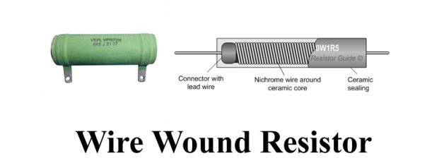
But technically a "good" dummy load is a resistor that has no RF characteristics. Why I mention this is many higher power resistors are constructed using a length of wire wrapped around a form. This is necessary to dissipate the heat because that's exactly what a resistor does, converts current into heat.

This is typically what they look like.

wire-wound-resistor.jpg

s-l1000-1.jpg
s-l1000.jpg


A wire wound resistor is fine for DC or low frequency such as audio. But for RF a typical wire wound resistor will look like an inductor. So like most things RF the real answer is "it depends" sort of.

Commercial dummy loads are built using several non-inductive (look for that statement) resistors in parallel or tuned so they aren't reactive at the frequencies you're interested in.

The catch here is unless you have a way to measure RF reactance you can't know if the resistor you have is going to produce artifacts at your frequencies. But if you had a piece of test equipment you knew worked then you probably don't need the dummy load in the first place.

dummy_load_full.jpg


The foolproof method is to use ten cheap 500Ω, 1W carbon resistors in parallel for 50Ω, 10W dummy load. It doesn't have to be pretty to work. In fact for CB you only need 5W so ten 1/2W 500 ohm resistors or even better is 20 1/4W 1K resistors, which might cost $1.

Dummy load resistors.jpg


https://m0zqr.blogspot.com/2012/05/building-dummy-load.html
 
Last edited:

rover67

Rising Sun Member
Joined
Nov 1, 2007
Messages
9,328
Location
Boulder, Co
Any luck with the watt meter Bruce?
 

60wag

Rising Sun Member
Joined
Aug 23, 2005
Messages
2,476
Yes I did a test yesterday and it worked quite well. I swept through the 1/2 wavelength region and found a sweet spot. I want to try it again in the 5/8 wavelength region to see how it compares to your numbers. I also checked the SBB1 stubby and the modified SB14. The SBB1 measured about 1.5 and the modified one was around 1.1. I guess whoever cut the thing down, did it properly, at least at the freq I was testing. I'll post more numbers later.
 

DaveInDenver

Rising Sun Ham Guru
Joined
Jun 8, 2006
Messages
13,114
Location
Grand Junction
A Comet SBB-1 will have a tuned SWR about 1.3:1 or so. Any better than that means you may have something wrong actually. Usually that means the antenna is short or long (e.g. not tuned to resonance) or the coax is acting like an impedance transformer or even part of the antenna or even could be the connector is a little resistive from a bad solder job or crimp.

For technical reasons see Marco's thread. Comes down to a 1/4λ whip will have a characteristic impedance of 36Ω which means with 50Ω coax feeding it you expect a slight discontinuity. I'm pretty sure I've mention it before but minimum SWR isn't always the goal. You want to measure what you expect. A "perfect" SWR of 1:1 only indicates there's no energy being reflected back. It doesn't indicate 100% of that energy is radiated.
 
Last edited:

60wag

Rising Sun Member
Joined
Aug 23, 2005
Messages
2,476
Here are my numbers. I ran the test twice, the second time starting with a much longer length of aluminum wire. I was hoping to see a dip in the 46" (5/8 wave range). The minor dip around 61" was unexpected. Once I hit the same length as the first test, it repeated rather well. I also tried the 38" CB steel whip on the SB14 base and was pleased to see the same result as the aluminum wire. I also repeated the measurements on the SBB1 and the SB14 modified mast. Both of those appear to be doing a well as possible, SWR anyway. The pic at the bottom shows the SBB1, the CB antenna and the modified SB14.

When measuring the SB14, the reflected power was very low, the needle moved but not much. If the wire and antenna aren't getting hot, where is the energy going besides being radiated?

Ham tune.JPG
antennas.jpg
 

DaveInDenver

Rising Sun Ham Guru
Joined
Jun 8, 2006
Messages
13,114
Location
Grand Junction
Can you clarify what base(s) you're using with the various whips?

The SB14 is a Comet SB14?

Are these numbers mounted or just on a bench? IOW, what's your counterpoise or ground plane? The SBB-1 and probably the CB whip will need the other half of their antennas. The SB14 might work fine on 2m without any plane. If you're not giving an antenna a counterpoise it'll find one, the coax shield, Earth, whatever it can to complete the RF circuit.

The SB14 was originally 1/4λ on 6m, 1/2λ on 2m and and collinear 5/8λ on 70cm. Since the two coil whip is gone it's hard to know what they did originally but I suspect the base has a matching network for 2 and maybe 70 and had no effect on 6m.

That meant the top coil may have been a choke for 2m and 70cm so the full whip was only necessary for 6m. The middle coil might only be needed for 70cm. So the final length of a plain whip for 2m would be 1/2λ or about 39" with no coils. It could be shorter with coils but might not be much different.

When measuring the SB14, the reflected power was very low, the needle moved but not much. If the wire and antenna aren't getting hot, where is the energy going besides being radiated?

In this case some amount of energy is consumed in the matching network. The overall efficiency is probably high so nothing should be getting hot. Heating means resistive losses, which is small in an antenna. The radiated RF doesn't generate any heat unless there's something to absorb it, which in the context of ham radio would be you, the operating meat bag. It's the principle behind a microwave oven - RF is generated that energizes cells and water, which vibrate and generate heat.

Reflected RF is harmful to the radio because it re-converts RF into heat, literally "burning up" electronics. A transceiver expects high power to only go out and very low power to come back. In receive the amount of energy it can tolerate is minuscule, the equivalent of milliwatts.
 
Last edited:

60wag

Rising Sun Member
Joined
Aug 23, 2005
Messages
2,476
This sacrificial whip I've been using is a length of 1/8" soft aluminum. I also tried the steel CB whip in the SB14 base to see if it produced similar numbers to my aluminum whip, which it did.

The base I've been testing on is the Comet SB14 base. It has a couple of set screws to mount the whip so its easy to swap whips.

The tests have been done with the mobile radio in my truck and the antenna mount on the rear hatch, so rear hatch and truck roof is my ground plane?

The info sheet for the SB14 descibes the coils as "phasing coils". I think I still have the base coil, fold over adapter, lower element, lower phasing coil and the upper element.

Thanks for the feedback.

SB14.JPG
 

DaveInDenver

Rising Sun Ham Guru
Joined
Jun 8, 2006
Messages
13,114
Location
Grand Junction
Yup, mounted on the truck makes sense. Whether it's a good counterpoise or not is a separate question, but it's a realistic test.

BTW, I mentioned this to Marco when he was testing. You don't have to use high power and it's easier on the radio if you don't. The SWR at 50 W is the same as it would be at 5 W or 500 mW. But it's doing more damage to the radio to ask it to use 50 W into a poor load and it'll protect itself. He found that even 2:1 SWR was enough to make a Kenwood start to reduce power and at 3:1 it had limited itself pretty significantly.
 
Top