Brucker
Hard Core 4+
The shop has been in need of a more graceful way of handling heavy objects then just our forklift. The shop is small and the scheduled is always packed, so shop space is limited, usually leading to having to move a bunch of equipment and various projects around in order to make room for forklift to maneuver. This eats up a lot of time and energy. Been also missing having an overhead hoist like the old shop had. It made loading the plasma table effortless. And with the new plasma table on the schedule to be finished up this year, as well as a couple vehicle body swaps, figured a solution should be found sooner than later.
Having looked at a lot of commercially available options and the price tags associated, nothing quite fit the bill. Decided to design and build exactly what was needed in house, rather than paying a pretty penny for something that wouldn't fit the needs perfectly without modification.
The crane needs to be capable of lifting and moving at least 1 ton (2000 pounds) of weight. But would like to build in a safety factor of at least twice the desired lifting capacity (so 2 ton overall capacity) to insure it will always be safe to use around the shop without pushing its limits. It will need at least one set powered hoists and trolleys. It needs be able to roll easily around the shop, but also stay locked into a certain position when called for. "A" framed sides would allow for the most clearance and maximum amount center leg length opposed to an upside down "T" or triangle side. So 4 high capacity swivel casters with brakes will be needed. But anyone who has tried to push around a heavy object on 4 swivel casters knows it can be a pain to keep tracking in the correct orientation. So swivel locks will be needed as well to aid in that process.
It will need to be wide enough to span the plasma table the short way (about 6' wide) while still being able to access the floor beside it for the loading and unloading of materials (up to 5' wide). It also needs to be able to lift a vehicle body off of it's chassis, move it next to the chassis, and be lowered down onto stands. Though it needs to be narrow enough to fit the long way through the shop's big overhead door (15.5' wide). And ideally as narrow as possible to save valuable space. So a 14' span between the legs and just over 14.5' overall width was chosen. The height was fairly straight forward. It needs to be able to fit out the lowest overhead shop door, and then extend to as how as the legs would allow. The lowest door is 94" tall so about 93.5" will be the shortest and there should be about 60" of total adjustment meaning the tallest would be about 153.5", or just over 12.5'. Given our highest ceiling is 12', this should work nicely.
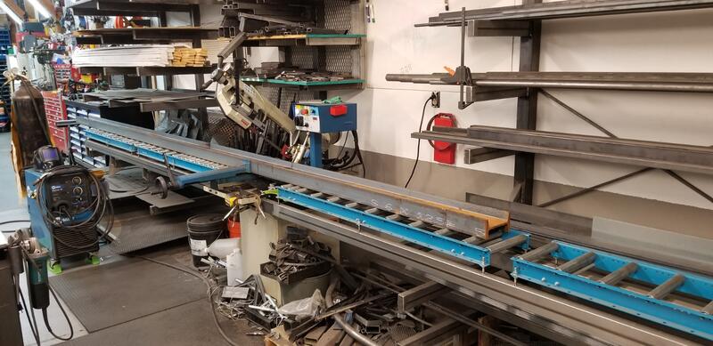
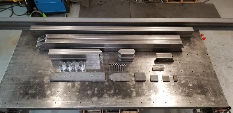
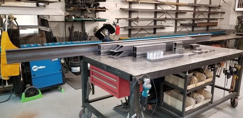
After running the numbers for the I beam, a design was quickly sketched up and a materials and cut lists were made and parts were ordered. I beam and the other materials were then cut to length on the swivel mast bandsaw and cleaned up with a flap disc on an angle grinder. Then the small parts were drilled and tapped as needed.
Short video of the caster plates being tapped with the old FlexArm tapping arm:
Having looked at a lot of commercially available options and the price tags associated, nothing quite fit the bill. Decided to design and build exactly what was needed in house, rather than paying a pretty penny for something that wouldn't fit the needs perfectly without modification.
The crane needs to be capable of lifting and moving at least 1 ton (2000 pounds) of weight. But would like to build in a safety factor of at least twice the desired lifting capacity (so 2 ton overall capacity) to insure it will always be safe to use around the shop without pushing its limits. It will need at least one set powered hoists and trolleys. It needs be able to roll easily around the shop, but also stay locked into a certain position when called for. "A" framed sides would allow for the most clearance and maximum amount center leg length opposed to an upside down "T" or triangle side. So 4 high capacity swivel casters with brakes will be needed. But anyone who has tried to push around a heavy object on 4 swivel casters knows it can be a pain to keep tracking in the correct orientation. So swivel locks will be needed as well to aid in that process.
It will need to be wide enough to span the plasma table the short way (about 6' wide) while still being able to access the floor beside it for the loading and unloading of materials (up to 5' wide). It also needs to be able to lift a vehicle body off of it's chassis, move it next to the chassis, and be lowered down onto stands. Though it needs to be narrow enough to fit the long way through the shop's big overhead door (15.5' wide). And ideally as narrow as possible to save valuable space. So a 14' span between the legs and just over 14.5' overall width was chosen. The height was fairly straight forward. It needs to be able to fit out the lowest overhead shop door, and then extend to as how as the legs would allow. The lowest door is 94" tall so about 93.5" will be the shortest and there should be about 60" of total adjustment meaning the tallest would be about 153.5", or just over 12.5'. Given our highest ceiling is 12', this should work nicely.
After running the numbers for the I beam, a design was quickly sketched up and a materials and cut lists were made and parts were ordered. I beam and the other materials were then cut to length on the swivel mast bandsaw and cleaned up with a flap disc on an angle grinder. Then the small parts were drilled and tapped as needed.
Short video of the caster plates being tapped with the old FlexArm tapping arm:
