Good Morning Neverland!
I had a couple of questions that hopefully some folks may know the answer to. I'm planning on upgrading my electrical system to a higher output alternator (thank you Bill) and a dual battery system. The previous owners had definately hacked the electrical system with multiple alarm systems and who knows what else, so this improvement is definately needed. Anyway, here's the first:
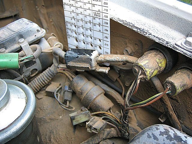
On the 85 4Runner (22RE) where is the fusable link located? The manual is not very clear on this (and it sort of indicates the fuse(s) in the fuse box located in the engine compartment. Odd. I'm enclosing a picture of something I don't recognize, which looks more like an in-line fuse coming from the alternator.
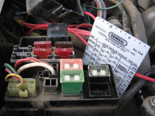
The second question is about the power going from the battery to the main fuse box. Has anyone taken apart this fuse box? It doesn't look too difficult, but I wanted to see if anyone had a procedure so I didn't mess it up. Hence the second picture. (Oh, and if someone has an image of the fuse assignments for this box, I would be much obliged if you could post it.)
The last question, for this morning, is about battery relocation. I was toying with the idea of relocating the spare tire inside the truck and placing one or both batteries in it's place. (Along with an air tank.) It seems like most people just bolt the batteries together, but I am inclined to put them in a box. I realize the batteries are sealed, but I think a bit of protection might be a good thing.
Thanks for your help.
the Other Matt
I had a couple of questions that hopefully some folks may know the answer to. I'm planning on upgrading my electrical system to a higher output alternator (thank you Bill) and a dual battery system. The previous owners had definately hacked the electrical system with multiple alarm systems and who knows what else, so this improvement is definately needed. Anyway, here's the first:
On the 85 4Runner (22RE) where is the fusable link located? The manual is not very clear on this (and it sort of indicates the fuse(s) in the fuse box located in the engine compartment. Odd. I'm enclosing a picture of something I don't recognize, which looks more like an in-line fuse coming from the alternator.
The second question is about the power going from the battery to the main fuse box. Has anyone taken apart this fuse box? It doesn't look too difficult, but I wanted to see if anyone had a procedure so I didn't mess it up. Hence the second picture. (Oh, and if someone has an image of the fuse assignments for this box, I would be much obliged if you could post it.)
The last question, for this morning, is about battery relocation. I was toying with the idea of relocating the spare tire inside the truck and placing one or both batteries in it's place. (Along with an air tank.) It seems like most people just bolt the batteries together, but I am inclined to put them in a box. I realize the batteries are sealed, but I think a bit of protection might be a good thing.
Thanks for your help.
the Other Matt
 5-pounder works great). I ran each neg. to the frame near the batts in the rear, then ran a ground cable from that location up to a tcase crossover bolt in the middle/front of the truck. From there I ran another cable to the block, and another to the body (smaller than 1/0; more like 2AWG).
 Electric motors, such as starters and winches, really do NOT like seeing less than rated voltage. EFI likes its ground to be really ground too, no floaty action for him, please. With 1/0, and with a 1/0 ground wire commoning the two ground points in addition to the frame, loops are not a concern.
