kurtnkegger
Rising Sun Member
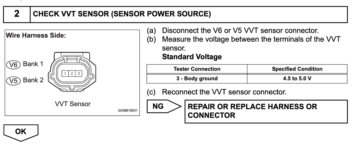
Wiring diagrams I've seen list power as VCV1 and VCV2. I am using that as my 5 volt reference, though theres nothing listed as a 5v wire.
vcv1 goes to the vvt sensors bank 2 intake and exhaust
vcv2 goes to the vvt sensors bank 1 intake and exhaust, Air swith valve bank 1, can shaft position sensor, and crankshaft position sensor.
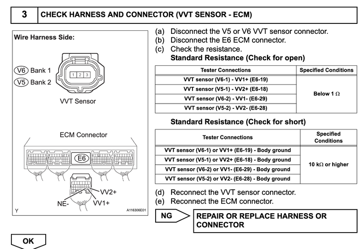
I cant get an ohm reading with my little fluke multimeter when I try to get ohms from pin6 and 14 to the chassis ground on pin 4. It automatically jumps to voltage when I try that. 6 and 14 together give me 62 ohms
vcv1 goes to the vvt sensors bank 2 intake and exhaust
vcv2 goes to the vvt sensors bank 1 intake and exhaust, Air swith valve bank 1, can shaft position sensor, and crankshaft position sensor.
I cant get an ohm reading with my little fluke multimeter when I try to get ohms from pin6 and 14 to the chassis ground on pin 4. It automatically jumps to voltage when I try that. 6 and 14 together give me 62 ohms