Fusible Links from battery on FJ62

Subrag

Rising Sun Member
Joined
Apr 8, 2010
Messages
27
Location
Conifer, Co
Hello,

I'm in the process of building the wiring harness for 3FE into FJ40 and I'm trying to figure out the fusible link sizes coming off the battery on page 1 section 1 of the wiring diagram. I have the FSM for the '88 62 but I don't see this described anywhere. There are five circuits running off the positive end of the battery. Example, the EFI fusible link shows 0.85R. There's also HEAD, ALT, AM1 and AM2 with 0.5G, 1.25B, 0.5G and 0.5G respectively. Also, what do the letters on the end mean?

As always, thanks for the help

Dave
 

Crash

Rising Sun Member
Joined
Aug 23, 2005
Messages
4,845
Location
Denver
The ‘88 FSM for the FJ62 is sorely lacking and is half the thickness of the ‘89 and ‘90 versions. Sounds like you have what you need, though. Sorry I don’t have answers to your questions.
 

Inukshuk

Rising Sun Member
Joined
Aug 24, 2005
Messages
8,695
Location
Denver, CO

DaveInDenver

Rising Sun Ham Guru
Joined
Jun 8, 2006
Messages
14,344
Location
Grand Junction
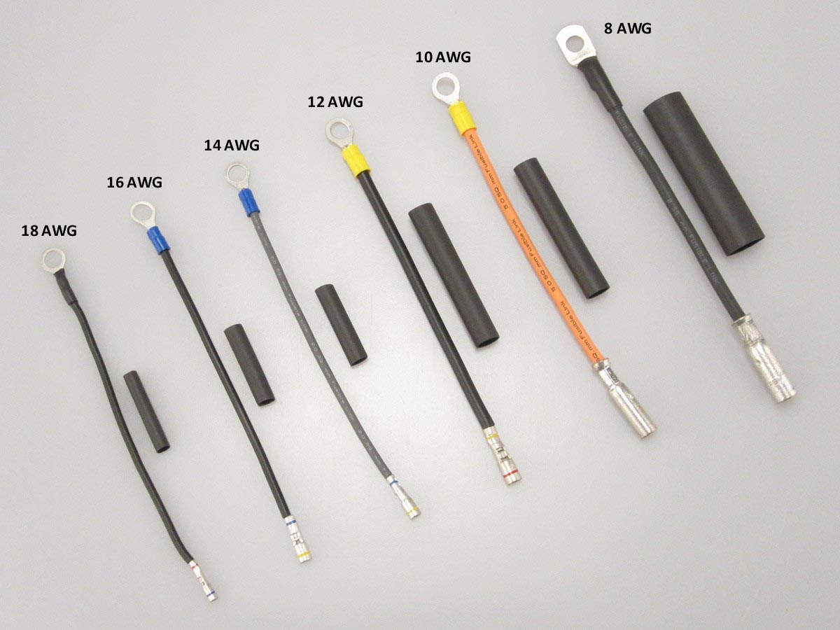
FYI on sizing fusible links. They are traditionally sized by wire size, not holding (breaking) current like fuses and breakers.

What "0.85R" means is cross section area of 0.85 square mm, which can't be directly converted to AWG (American Wire Gauge). This is slightly larger than 18 AWG by the numbers (18 AWG = 0.822 mm^2).

The basic rule of thumb is to size a fusible link by stepping down two gauges from the wire protected. A 2.00 mm^2 wire (14 AWG) wire is protected by a 0.85R (18 AWG) fusible link.

For general reference the metric to SAE fusible link size cross (this is NOT protected wire size).

0.30 -> 22 AWG
0.50 -> 20 AWG
0.85 -> 18 AWG
1.25 -> 16 AWG
2.00 -> 14 AWG
3.00 -> 12 AWG
5.00 -> 10 AWG

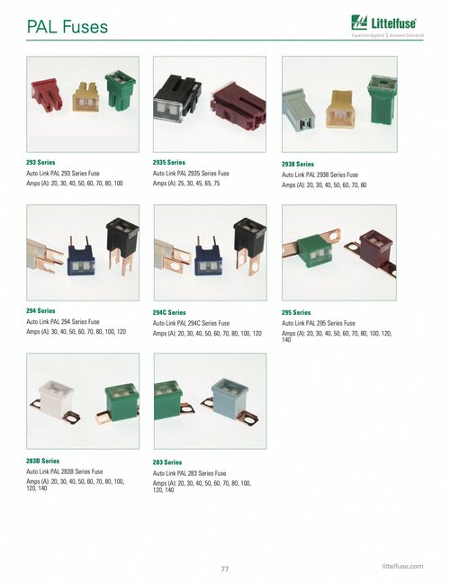
Fusible links are still used and viable. Toyota uses them, they just look different now. PAL meaning Pacific Auto Link.

The reason behind this is a fusible link has a different fault characteristic used in high amp, low duration protection such as starting circuits compared to fuses or breakers. It's possible to convert if you know the time-current nature of your load and wire.

From an engineering perspective one is not better or worse than the other at the job of protecting a wire. They are just different. Practically speaking fuses are of course more convenient to size, mount and replace, although the PAL type solves much of that. You can't use fusible links to protect loads and devices but as protection for wire they are completely fine. It's also not just a question of cost. There's benefits such as fusible links require no temperature derating (they follow the same profile as the protected wire itself) when used in the engine bay and they have fewer issues in the presence of chemicals and oils, mainly with unsealed terminal corrosion. Point I'm making is don't feel it is absolutely necessary to replace fusible links with fuses from a performance or safety aspect. That said, the only times I've ever intentionally specified fusible links was on a commercial truck application where some standards as written preferred them.

Passenger-Car-Catalog.jpg
 
Last edited:

Subrag

Rising Sun Member
Joined
Apr 8, 2010
Messages
27
Location
Conifer, Co
DaveInDenver,

Thanks for that. Do you know what the letters on the end means? I see G, B and R.

Dave
 

DaveInDenver

Rising Sun Ham Guru
Joined
Jun 8, 2006
Messages
14,344
Location
Grand Junction
DaveInDenver,

Thanks for that. Do you know what the letters on the end means? I see G, B and R.

Dave
I don't. It could be a place holder for "square millimeter" or maybe a color. You sometimes see in Japanese cars that 0.85 is red in color (so 0.85R?). Brown is often 0.30, Green is 0.5, Black 1.00 or 1.25. I'm not aware of standard for this, if there is one.

In other contexts R is a place holder for multiplier, such as 1R0 and 01R on a resistor the R is a 0.01 multiplier (in that case meaning 1 ohms depending on the standard for marking, such as two digits precision 01R is 100 x 0.01 = 1.00 ohms) so it could be used in this context to mean 85R = 85 x 0.01 = 0.85 and the sectional area dimensions are implied. This would my guess behind it.
 
Last edited:

Crash

Rising Sun Member
Joined
Aug 23, 2005
Messages
4,845
Location
Denver
The OEM FJ62 fusible link was uber simple and, I’m guessing, super cheap and easy to install on the factory floor. It’s a shame they are no longer available from Toyota.
 

Inukshuk

Rising Sun Member
Joined
Aug 24, 2005
Messages
8,695
Location
Denver, CO
I was today years old when I learned the PAL "fuses" are the new alternative to fusible links!
 

Subrag

Rising Sun Member
Joined
Apr 8, 2010
Messages
27
Location
Conifer, Co
This place has kits to make your own or they will make them for you.

Is there any issue with connecting the fusible link to a terminal block before connecting to the circuit? It seems it would be easier to replace if needed.

Dave
 

DaveInDenver

Rising Sun Ham Guru
Joined
Jun 8, 2006
Messages
14,344
Location
Grand Junction
I was today years old when I learned the PAL "fuses" are the new alternative to fusible links!
Understand that PAL are not 1-for-1 exactly the same as a wire fusible link. They solve a problem where designers didn't think fuses at the time were quite the right thing. These days MEGA, MAXI, ANL, MIDI, ZCASE and MRBF are potential alternatives. Consult your datasheets looking at the time-current characteristics, mix in some mechanical limits, how much space you have and your budget. The cartridge aspect of PAL makes sense for OEMs but that might not help them make sense doing aux circuits, repairs or retrofits.
Is there any issue with connecting the fusible link to a terminal block before connecting to the circuit? It seems it would be easier to replace if needed.
It's not typical to do that but as long as it's only a single wire being fed/protected it may work.

The main problem is a terminal block could be it's own neck so you'd need to make sure the connection has negligible added resistance and voltage drop. The last thing you want is a terminal strip or block being the sacrificial part that melts.

For a 14 AWG wire/18 AWG fusible link you may be OK with a nice, big block. But very large ones (like to the battery or starter) I'd advise to stick with the butt connector. The crimped butt connector you normally use for a fusible link repair adds some resistance strictly speaking but it's a minor issue.

One thing you do not want to do is rely on a solder terminal for a fusible link. Things get hot enough to melt copper when a fusible link opens and this temperature is higher than the melt point of solder. Fusible link wire must be crimped connections to be reliable.
 
Last edited:

Inukshuk

Rising Sun Member
Joined
Aug 24, 2005
Messages
8,695
Location
Denver, CO
Fixed it:
Consult your @DaveInDenver. The cartridge aspect of PAL makes sense for OEMs but that might not help them make sense doing aux circuits, repairs or retrofits.


One thing you do not want to do is rely on a solder terminal for a fusible link. Things get hot enough to melt copper when a fusible link opens and this temperature is higher than the melt point of solder. Fusible link wire must be crimped connections to be reliable.
Great info
 

Cruisertrash

Hard Core 4+
Joined
Aug 18, 2020
Messages
3,108
Location
Denver
Thanks for the shout Daniel. I stopped advertising my stuff here because there was zero interest in it. Lots of orders every week, just none from Rising Sun!

Anyway, yes @Subrag I make a kit to replace the fusible links that's designed for an FJ62 (the wiring harness you apparently have), as well as for FJ60s, along with some other non-US 60 Series variants. @Crash is running prototype #1 of the FJ62 kit that I installed in his truck quite a while ago now. Since then I've sold maybe 100 of the kits. Pros and cons to a fused setup versus fusible links - mostly all pros though, at least in my opinion.

I also have fusible link wire and can rebuild existing links. I prefer not to do that because I think my replacement kit offers many, many advantages, but I am occasionally convinced. The fusible links are discontinued for the 62 so the only other option you're left with is scrounging one up from the overpriced junk hawkers on eBay. With this build being for a 40, you may consider altering the harness. The FJ62 has a lot of widgets in the cabin like heaters, lights, defrost, etc, that your 40 may not have or need. If you're dropping some of that stuff you could customize the harness and customize the fuse protection you need. Not sure how deep you're going on this, though.

@DaveInDenver has tons of great technical expertise as usual. I caution not to lose sight of the forest for the trees, however. Fusible links - in the form factor used on the 60 Series - take up less space which is great, and they're very simple. On the negative side they're now getting very difficult to find and it's difficult to find a consistent source for link wire to rebuild them. There's one place in the world (not in the US) where you can get true metric link wire. They're prone to corrosion as well as damage from heat over time, which changes their safety characteristics. They have higher resistance than the wire they protect so they generate heat and cause a voltage drop. It's a convenience & simplicity trade-off versus performance.
 

DaveInDenver

Rising Sun Ham Guru
Joined
Jun 8, 2006
Messages
14,344
Location
Grand Junction
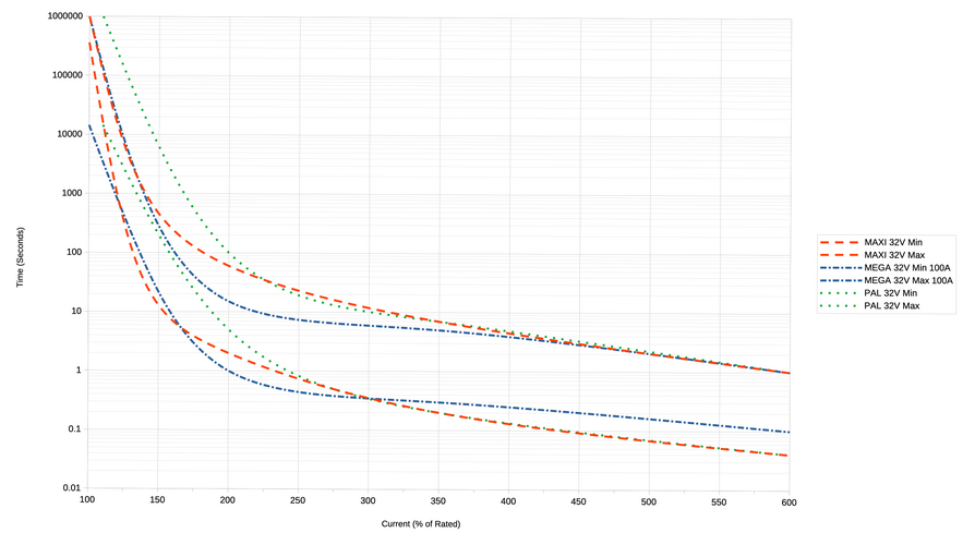
I need to make a clarification to my implied operating curve of PAL fuses. They are slow-ish open. You can start to see the abruptness of a fuse compared to a fusible link.

threetypesfusescompared.png

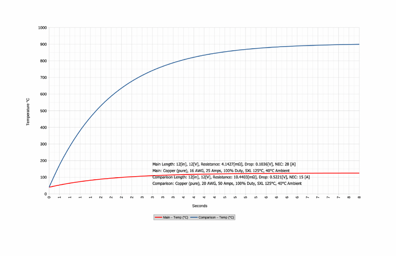
It's not a perfect comparison but if you take a 16 AWG protected with a 20 AWG it'll look vaguely like this. The melt temp of copper is 1,083°C so the 20 AWG would reach that in a few seconds at 200% (e.g. 50A assuming 25A is nominal current). This isn't a simple thing to calculate or show. Depending on how I do it one formula suggest 1.46 seconds for a 20 AWG to reach melt at 50A while another says a 20 AWG will take 74A short circuit current for 1 second. Another chart tells me the 5 second fusing current for 20 AWG is 58A. You normally look at steady state temperature rise of a conductor to stay under the insulation limit on the order of 600 seconds so the equations behind these curves are not ideal for very fast large current application.

heating_using_fusiblewire.png
 
Last edited:

Subrag

Rising Sun Member
Joined
Apr 8, 2010
Messages
27
Location
Conifer, Co
CruiserTrash,

I'd be interested in seeing what you have. I have a complete 62 harness and pulling out what's needed to make the EFI "custom" harness to go in the 40.

Are you around this weekend or are you going to the Expo?

Dave
 

Cruisertrash

Hard Core 4+
Joined
Aug 18, 2020
Messages
3,108
Location
Denver
CruiserTrash,

I'd be interested in seeing what you have. I have a complete 62 harness and pulling out what's needed to make the EFI "custom" harness to go in the 40.

Are you around this weekend or are you going to the Expo?

Dave
I won’t be at the expo, but I’ll be at my shop wrenching Sunday morning and most of the day Monday. These spring bushings and drum brakes aren’t going to fix themselves! My shop is near where Rocky’s Autos used to be near Federal & 64th.

I don’t have a complete 62 kit on hand to show you - I ran out of some components that go into it and I’m waiting for their arrival - but I have the similar kit on my 60 that demonstrates the concept.

More info and photos can be found here.
 
Back
Top