Centering the Front Axle

subzali

Hard Core 4+
Joined
Aug 22, 2005
Messages
10,322
Location
Denver CO
Staying home from skiing due to me getting stuck in traffic on Floyd Hill and throwing in the towel at Clear Creek has allowed me to get a lot of catching up done :D I've only had these pictures for 1 1/2 months :rolleyes:

I wanted to do this because my axle only lasted about 10,000 miles (2 years) before it started leaking again, I felt the shaft and there's no groove in it and it turned out that my shims were a fair bit off.

This isn't really a step-by-step, but a picture help of what actually needs to happen with a couple suggestions to make it a little easier: it was interesting for me to see how the centering tool works, so I thought I would share, sorry for the horrible pictures though, I need to get a real camera. Instructions come with the tool though, so I assume you will have those present when performing this task.

Tools you will need (in addition to front axle tools and SST, OTC Tools # 09634-60014):
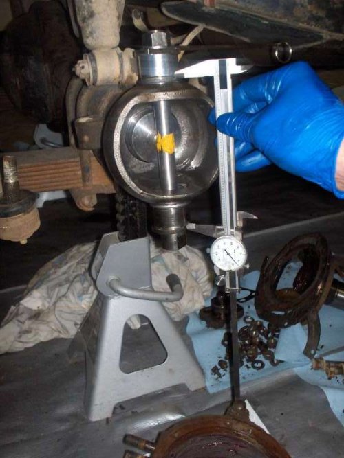
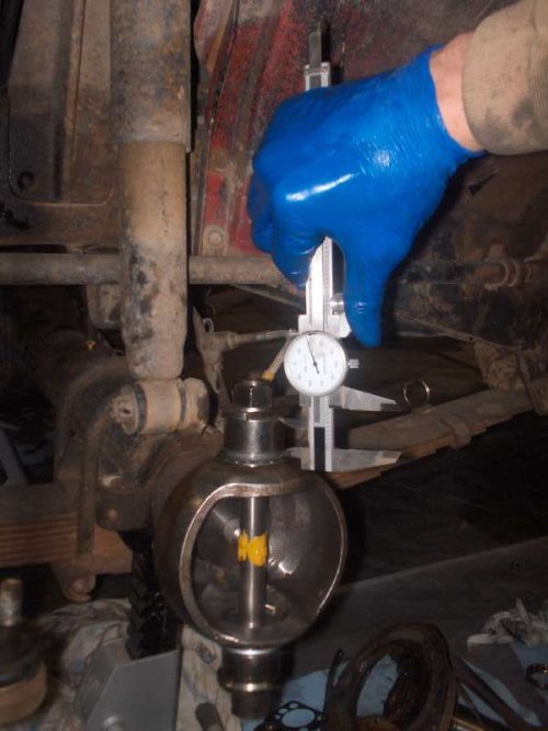
-A caliper that is longer than 6", though you can make a 6" one work if you take good measurements. The shims come in certain sizes anyway so +/- 0.003 or 0.005 inches is not going to make a difference.
-fish scale for preload, or just feel that the lever is snug.
-wrenches for tightening nuts, I think 19mm and/or 3/4" work, and you'll need a 24mm or 15/16" as well.
-some kind of marking compound, the instructions say to use lead, but that didn't give me a good feeling so I used gear marking compound. EDIT: Antisieze also works well to mark the shaft.
-Allen wrench
-Vise grips (to hold the allen wrench)

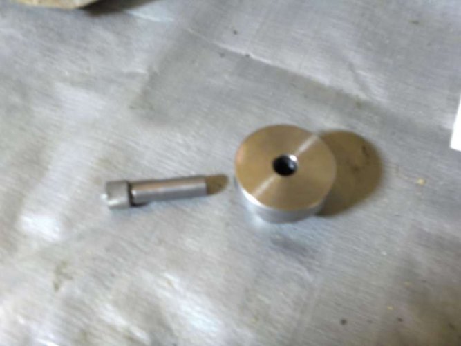
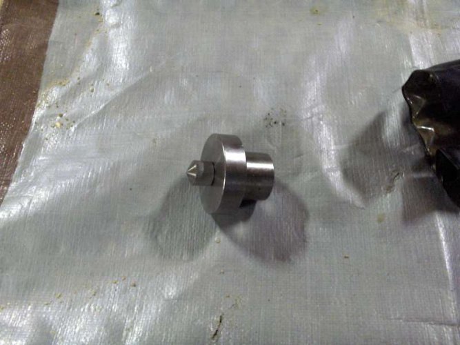
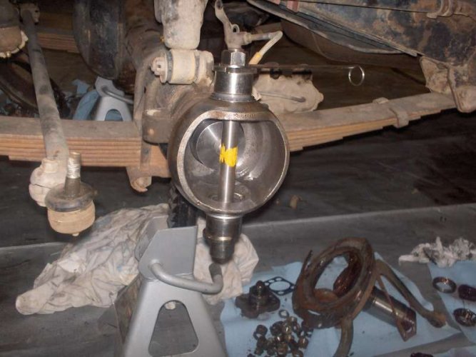
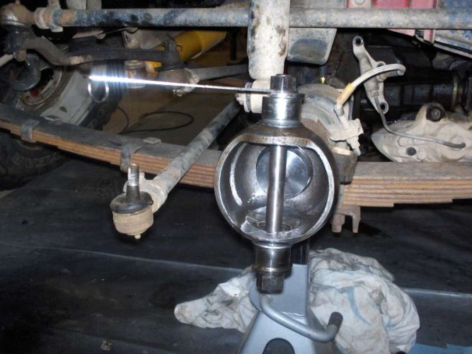
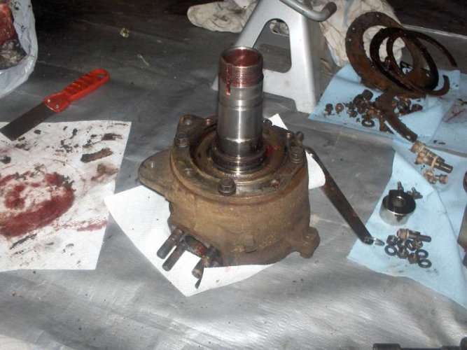
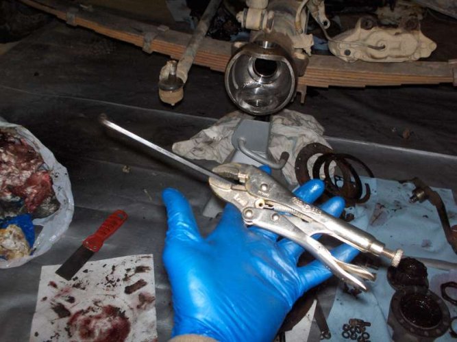
1. You strip the knuckle all the way down to the bare housing. You take out the inner oil seal and slide in this sleeve (it's a tight fit, I found that an allen wrench works well in getting it out)
 

Attachments

  • HPIM3101.jpg
    HPIM3101.jpg
    43.9 KB · Views: 641
  • HPIM3119.jpg
    HPIM3119.jpg
    53.5 KB · Views: 611
Last edited:

subzali

Hard Core 4+
Joined
Aug 22, 2005
Messages
10,322
Location
Denver CO
2. Then you take the other collar and marking spindle and slide them together and slide them into the axle housing.
 

Attachments

  • HPIM3102.jpg
    HPIM3102.jpg
    21.5 KB · Views: 615
  • HPIM3103.jpg
    HPIM3103.jpg
    40.3 KB · Views: 601
  • HPIM3106.jpg
    HPIM3106.jpg
    49.9 KB · Views: 609

subzali

Hard Core 4+
Joined
Aug 22, 2005
Messages
10,322
Location
Denver CO
3. *The knuckle bearings and races have to be intact for this next step* Take the other pieces and assemble them in the order shown, the directions that come with the tool tell how much preload you need on the handle. I used gear marking compound on the shaft; it worked pretty well. You take the measurement that is laid out in the documentation.
 

Attachments

  • HPIM3110.jpg
    HPIM3110.jpg
    48.7 KB · Views: 634
  • HPIM3109.jpg
    HPIM3109.jpg
    46.7 KB · Views: 592
  • HPIM3108.jpg
    HPIM3108.jpg
    51.3 KB · Views: 646
  • HPIM3107.jpg
    HPIM3107.jpg
    49.8 KB · Views: 914
  • HPIM3112.jpg
    HPIM3112.jpg
    38.9 KB · Views: 615

subzali

Hard Core 4+
Joined
Aug 22, 2005
Messages
10,322
Location
Denver CO
4. Next is to take measurements on the knuckle housing: first you must bolt the spindle onto the housing. Then you insert the marking spindle and collar into the front axle spindle. This is where I had problems: the bearings are a fairly tight fit onto the marking shaft but you have to slide both of them off in order to mount the marking shaft to the knuckle housing. How you do that without messing up your mark on the measuring shaft is a mystery to me (in the instructions it indicates that you need to not disturb the mark you made on the measuring shaft). However, if you take measurements before you slide the bearing off then you should be good to go. Then you mount up the measuring device onto the knuckle housing and make another mark.
 

Attachments

  • HPIM3115.jpg
    HPIM3115.jpg
    52.5 KB · Views: 590
  • HPIM3116.jpg
    HPIM3116.jpg
    54.1 KB · Views: 589
  • HPIM3117.jpg
    HPIM3117.jpg
    57.2 KB · Views: 692

subzali

Hard Core 4+
Joined
Aug 22, 2005
Messages
10,322
Location
Denver CO
That's it! Remove the pieces of the tool, clean them and put them away, use your A,B, and C measurements (that the instructions talk about) to find the closest match to the shims you have available to you, and put your axle back together. One other thing: the measuring spindle WILL scratch the shaft, so since only a light touch is needed to make a mark in the marking compound make sure you press lightly; the tool I borrowed had been boogered up by previous users and it made it harder to make accurate measurements.
 

corsair23

Hard Core 4+
Joined
Jul 11, 2006
Messages
8,610
Location
Littleton
Nice write up Matt :thumb:
 

RockRunner

Hard Core 4+
Joined
Nov 19, 2006
Messages
4,431
Location
Roxborough
Very nice write up Matt. I never did that with my front end:eek:, just used the fish scale and matched the shims from before, I did use new ones.

May have to get a centering tool if I get the Bobby longs before Moab..........:D

Great Job :thumb:
 

subzali

Hard Core 4+
Joined
Aug 22, 2005
Messages
10,322
Location
Denver CO
Thanks for the comments guys, I only did this because it started leaking so soon after my first rebuild - on the first time I reused the shims like most people do. So we'll see if this lasts any longer.

There are two shim thicknesses:
43233-60010 is 0.2mm (0.008") and
43234-60010 is 0.5mm (0.020")

I started with the following (For the Driver's Side):
Driver's Side Bottom: 0.040" (2 x 0.020")
Driver's Side Top: 0.039" (2 x 0.020")

The total adjusting shim thickness I needed was 2.5mm (0.098")
Driver's. Side Bottom Needed: 1.2mm (0.046") (0.006" off from what I had)
Driver's. Side Top Needed: 1.3mm (0.052") (0.013" off from what I had)

Because there are only two sizes available I had to get as close as possible, so:
Driver's. Side Bottom Used: 1.2mm (0.048") (2 x 0.020" + 1 x 0.008") (0.002" off from req'd)
Driver's. Side Top Used: 1.0mm (0.040") (2 x 0.020", determined by preload) (0.012" off from req'd)

I started with the following (For the Passenger's Side):
Pass. Side Bottom: 0.048" (2 x 0.020" + 1 x 0.008")
Pass. Side Top: 0.048" (2 x 0.020" + 1 x 0.008")

The total adjusting shim thickness I needed was 2.4mm (0.095")
Pass. Side Bottom Needed: 1.6mm (0.063") (0.015" off from what I had)
Pass. Side Top Needed: 0.8mm (0.032") (0.016" off from what I had)
*As you can see this one was offset by quite a bit*

Because there are only two sizes available I had to get as close as possible, so:
Pass. Side Bottom Used: 1.5mm (0.060") (3 x 0.020") (0.003" off from req'd)
Pass. Side Top Used: 0.9mm (0.036") (1 x 0.020" + 2 x 0.008") (0.004" off from req'd)

HTH
 
Last edited:
Top